Phase-change structural insulated panels and walls

a technology of structural insulation and insulated panels, applied in the field of structural insulation panels and walls, can solve the problems of increasing the flammability of the boards, reducing the permeability of the boards to water vapor, and wasting engineering and design time, and achieve the effect of high strength

Inactive Publication Date: 2005-03-17
KANSAS UNIV OF
View PDF29 Cites 73 Cited by
  • Summary
  • Abstract
  • Description
  • Claims
  • Application Information

AI Technical Summary

Benefits of technology

[0009] It is an object of the present invention to provide a

Problems solved by technology

This in turn can save time on engineering and design costs.
However, the imbibed method results in increased flammability of the boards.
In addition, the PCMs are often wax-like materials, which decrease

Method used


Image

  • Phase-change structural insulated panels and walls
  • Phase-change structural insulated panels and walls
  • Phase-change structural insulated panels and walls

Examples


Embodiment Construction

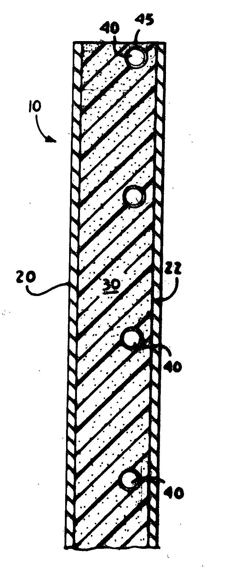
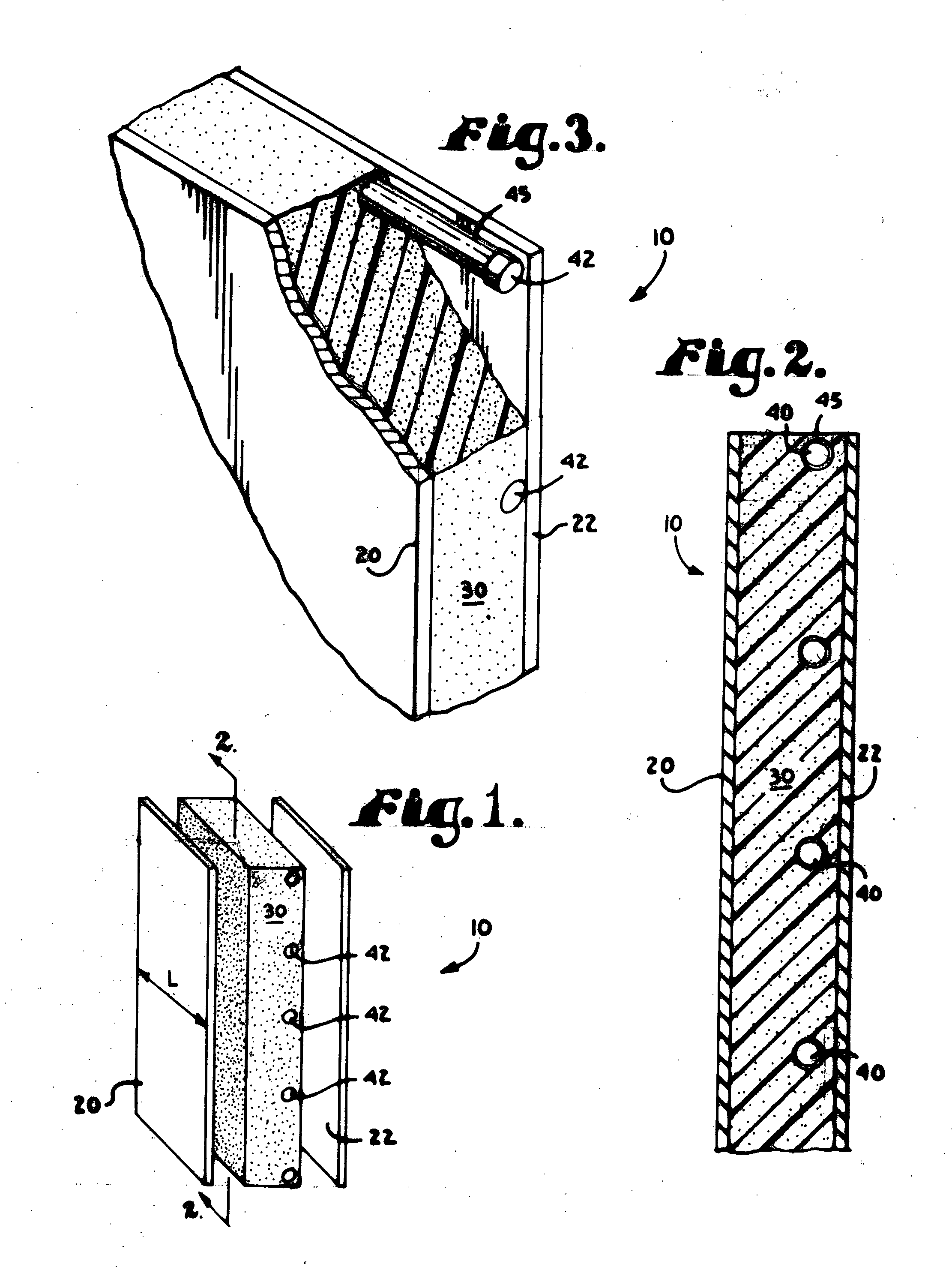
[0020] Referring to FIGS. 1-2, a structural panel in accordance with the present invention is shown. Structural panel 10 includes first and second sheathings 20 and 22 disposed on and affixed to opposed outer surfaces of a generally planar, insulating core 30. One or more PCMs 40 are macroencapsulated between the sheathings 20, 22.

[0021] Various types of sheathings 20, 22 are known to those skilled in the art. The sheathing is preferably comprised of a rigid material such as gypsum or cementous composite, waferboard, metal, plywood, drywall, OSB, or an agricultural board product such as strawboard or wheatboard. Most preferably, the sheathing comprises OSB.

[0022] The sheathings 20, 22 of the present invention are of any suitable thickness. The sheathing preferably has a thickness between about 0.125 to 3 inches (7.18 mm to 7.62 cm), more preferably between about 0.25 to 2 inches (6.35 mm to 5.08 cm), and most preferably about 0.5 to 0.75 inches (1.27 to 1.91 cm). Common commercial...


PUM


Abstract

A wall, ceiling, or structural insulated panel having macroencapsulated phase-change materials incorporated therein.

Description

CROSS-REFERENCE TO RELATED APPLICATIONS [0001] None. STATEMENT REGARDING FEDERALLY SPONSORED RESEARCH OR DEVELOPMENT [0002] None. FIELD OF THE INVENTION [0003] The present invention relates to structural walls and ceilings, and more specifically to a structural insulated panel and wall having macroencapsulated phase-change materials incorporated therein. DESCRIPTION OF RELATED ART [0004] In the construction of various types of buildings, the walls, roofs, ceilings and floors are typically designed to thermally insulate the space enclosed thereby. In this regard, a variety of different construction techniques have been devised. [0005] Conventional frame construction is widely employed in residential and other types of construction. Typically, a wood frame for the structure is constructed with load-bearing walls comprising studs, top and bottom plates, and headers over the openings. Floor and ceiling joists span between the walls. During or after the framing stage, sheathing is typica...

Claims


Application Information

Patent Timeline
IPC IPC(8): E04B1/80E04C2/292E04C2/296F28D20/02
CPCE04B1/80E04C2/292F28F2270/00F28D20/02Y02E60/145E04C2/296F28D20/023Y02E60/14
Inventor MEDINA, MARIO A.
Owner KANSAS UNIV OF
Why Eureka
Try Eureka