Heat exchanger module

a technology of heat exchanger and module, which is applied in the direction of subcoolers, machines/engines, light and heating apparatus, etc., can solve the problems of insufficient function of components and difficulty in sufficiently and achieve the effect of increasing the capacity of modulators

Active Publication Date: 2005-03-17
DENSO CORP
View PDF4 Cites 31 Cited by
  • Summary
  • Abstract
  • Description
  • Claims
  • Application Information

AI Technical Summary

Benefits of technology

[0006] In view of the above-described problems, it is an object of the present invention to provide a heat exchange module including a modulator (gas

Problems solved by technology

However, when high-pressure side equipments of the vapor compression refrigerant cycle and a cooling heat exchanger on a vehicle side are simply combined, the function of the components cannot be sufficiently obtained.
For example, when the oil

Method used


Image

  • Heat exchanger module
  • Heat exchanger module
  • Heat exchanger module

Examples


first embodiment

[0017] (First Embodiment)

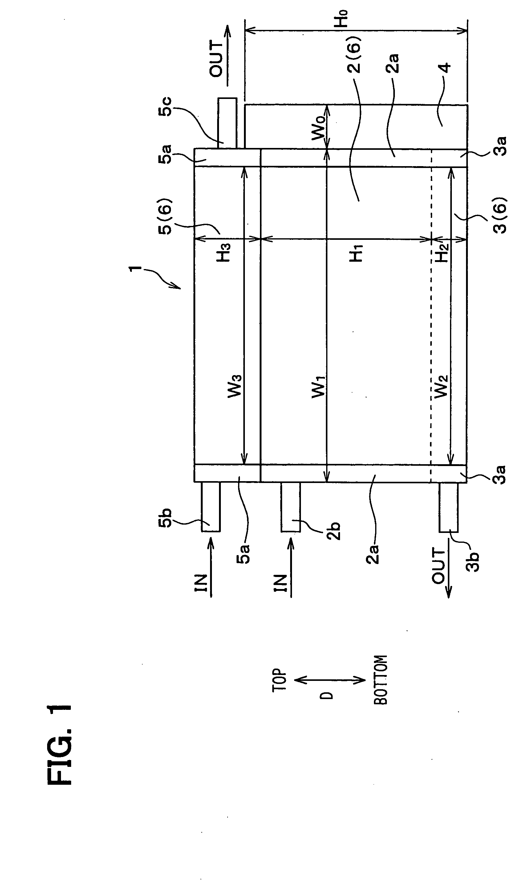
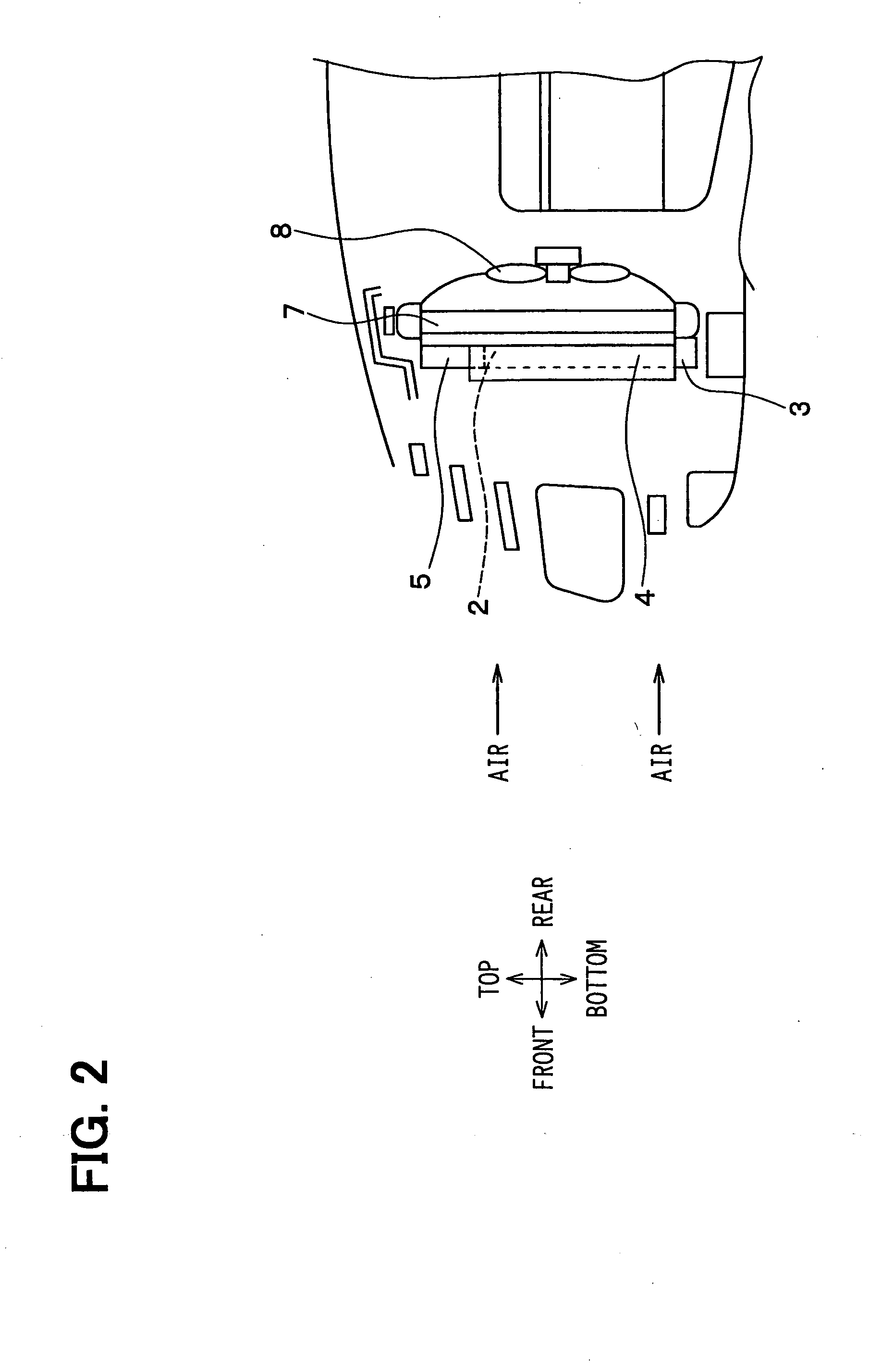
[0018] In the first embodiment, a cooling heat exchanger module 1 of the present invention is typically used for a cooling device of a vehicle. FIG. 1 is a front view of the cooling heat exchanger module 1 when being viewed from a downstream air side of the cooling heat exchanger module 1.

[0019] As shown in FIG. 1, the heat exchanger module 1 in this embodiment includes: a condenser 2 (refrigerant radiator), a sub-cooler 3 and a modulator 4 (gas-liquid separator) of a vapor compression refrigerant cycle for a vehicle air conditioner; and an oil cooler 5 for cooling an engine oil or an automatic transmission fluid (ATF) of the vehicle.

[0020] The condenser 2 is a high-pressure heat exchanger for cooling and condensing high-temperature and high-pressure refrigerant discharged from a compressor of the vapor-compression refrigerant cycle. The sub-cooler 3 is a super-cooling device for further cooling the liquid refrigerant condensed in the condenser 2 so as to ...

second embodiment

[0038] (Second Embodiment)

[0039] The second embodiment of the present invention will be now described with reference to FIG. 3. In the above-described first embodiment, the connection pipe 5c is connected to a side surface of the oil cooler 5, where the modulator 4 extends. In this case, because it is necessary to prevent an interference between the connection pipe 5c and the modulator 4, the height dimension H0 of the modulator 4 cannot be enlarged to a dimension equal to the sum of the height dimension H1 of the condenser 2, the height dimension H2 of the sun-cooler 3 and the height dimension H3 of the oil cooler 5.

[0040] In the second embodiment, as shown in FIG. 3, the connection pipe 5c is connected to the oil outlet of the oil cooler 5 to extend in a direction parallel to the air flow direction. In this case, it can prevent the modulator 4 from being interfered with the connection pipes 5c. Accordingly, in the second embodiment, it is possible to increase the height dimension...

third embodiment

[0041] (Third Embodiment)

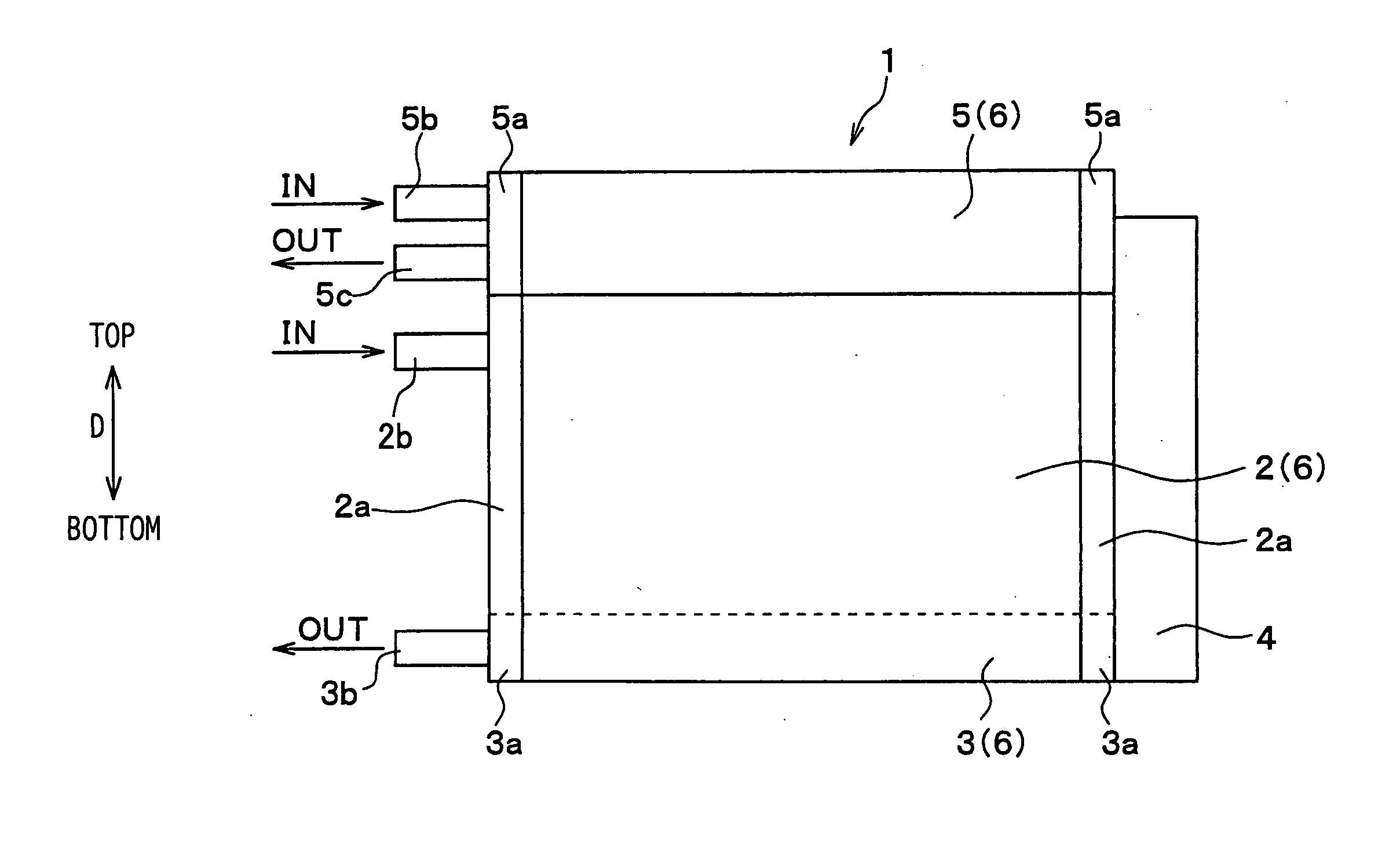
[0042] In the above-described second embodiment, the connection pipe 5c connected to the oil outlet of the oil cooler 5 is provided to protrude in the direction parallel to the air flow direction. However, in the third embodiment, as shown in FIG. 4, both the connection pipe 5b connected to the oil inlet of the oil cooler 5 and the connection pipe 5c connected to the oil outlet of the oil cooler 5 are provided at a side of the header tank 5a, opposite to the modulator 4 with respect to the oil cooler 5. That is, both the connection pipes 5b and 5c are connected to the left header tank 5a in FIG. 4, and the modulator 4 is provided adjacent to the right header tank 5a in FIG. 4. Accordingly, it can prevent the modulator 5 and the connection pipe 5c from being interfered with each other.

[0043] Thus, in the third embodiment, it is possible to increase the height dimension H0 of the modulator 4 to the dimension equal to the sum of the height dimension H1 of the ...


PUM


Abstract

A heat exchanger module includes a condenser for condensing a refrigerant, a modulator, a sub-cooler for cooling liquid refrigerant supplied from the modulator, and a heat exchanger for cooling a fluid different from the refrigerant. The condenser, the sub-cooler and the heat exchanger are arranged in an arrangement direction substantially perpendicular to an air flow direction. Further, the modulator is disposed to extend in the arrangement direction. In the heat exchanger module, the modulator has a dimension that is larger than the sum of a dimension of the condenser and a dimension of the sub-cooler, and is not larger than the sum of the dimension of the condenser, the dimension of the sub-cooler and a dimension of the heat exchanger, in the arrangement direction. Accordingly, a capacity of the modulator can be effectively increased without increasing a largest outer side of the heat exchanger module.

Description

CROSS REFERENCE TO RELATED APPLICATION [0001] This application is based on Japanese Patent Application No. 2003-322973 filed on Sep. 16, 2003, the disclosure of which is incorporated herein by reference. FIELD OF THE INVENTION [0002] The present invention relates to a heat exchanger module constructed with a cooling heat exchanger in which refrigerant of a vapor compression refrigerant cycle flows such as a condenser and a sub-cooler, and a cooling heat exchanger such as an oil cooler in which a fluid different from the refrigerant flows. The heat exchanger module is suitably used for a cooling device of a vehicle. BACKGROUND OF THE INVENTION [0003] When plural heat exchangers are arranged in a serious in an air flow direction, a dimension of a heat exchanger module composed of the plural heat exchangers in the air flow direction becomes larger. Thus, in a conventional heat exchanger module (e.g., JP-A-2001-174168, U.S. Pat. No. 6,394,176), plural heat exchangers are arranged in a d...

Claims


Application Information

Patent Timeline
IPC IPC(8): B60K11/04F01P3/18F25B39/04F25B40/02F25B1/00F28D1/04F28D1/053
CPCB60K11/04F01P2003/182F01P2060/04F01P2060/14F28F2009/0287F25B40/02F25B2339/044F25B2500/01F28D1/0443F25B39/04F28D1/053
Inventor SANADA, RYOUICHI
Owner DENSO CORP
Why Eureka
Try Eureka