Coating head and coating apparatus

a coating head and coating technology, applied in the field of coating head and coating apparatus, can solve the problems of reduced product quality, inability to completely solve problems, and sometimes occuring fine streak defects in coating films, so as to achieve the effect of reducing disturbance in coating films and improving surface roughness after working

Active Publication Date: 2005-03-17
FUJIFILM CORP +1
View PDF6 Cites 3 Cited by
  • Summary
  • Abstract
  • Description
  • Claims
  • Application Information

AI Technical Summary

Benefits of technology

[0013] According to the present invention, it is preferred that a recess extending along the width direction of the supporting member is formed in the back edge back surface. It is preferable to perform grinding as surface finishing on the back edge back surface. If such a recess extending along the width direction of the supporting member is formed, a grinding wheel used for grinding does not interfere with any portion other than the worked surface and, therefore, the finished condition of the worked portion of the back edge back surface is good. The present invention is effective in this respect.
[0014] According to the present invention, it is preferred that the surface roughness Ra of the portion of the back edge back surface between the position at which the back edge back surface intersects the back edge surface and a position at a distance of 0.5 mm from the intersecting position is 0.2 μm or less. By defining the portion having a suitable surface roughness at least by this distance, full use of the effect of the present invention can be made.
[0015] According to the present invention, it is also preferred that the distance between the position at which the back edge back surface intersects the back edge surface and the recess is 0.5 mm or greater. By defining the portion having a suitable surface roughness at least by this distance, full use of the effect of the present invention can be made.
[0016] According to the present invention, it is also preferred that each of the back edge surface and the back edge back surface is formed by a sintered hard alloy or a ceramic. By using such a material for the back edge surface and the back edge back surface, the surface roughness after working can be improve to make full use of the effect of the present invention.
[0017] According to the present invention, as described above, the coating head has a slit, a front edge surface, a back edge surface and a back edge back surface intersecting the back edge surface by forming a predetermined angle therebetween, and the surface roughness Ra of the back edge back surface is 0.2 μm or less. This arrangement ensures that disturbance in the coating film is effectively reduced and substantially no fine equal-pitch streaks are generated.

Problems solved by technology

The above-described extrusion application methods, however, entail a specific problem that a fine streak defect sometimes occur in coating film.
There is a possibility of a reduction in product quality resulting from this defect.
Under present circumstances, this problem cannot be completely solved by any of the methods described in the publications Nos. 5-8065, 6-77712 and 2942938.
Even in a case where such an apparatus, for example, one arranged to set the surface roughness Ra of a predetermined portion to 5 μm or less and 0.7 μm at the minimum is used, fine streaks appear with a constant pitch of several hundred microns when thin-coating coating is performed by setting a coating thickness to 10 μm or less in a wet condition, and the effect is not satisfactory.

Method used


Image

  • Coating head and coating apparatus
  • Coating head and coating apparatus
  • Coating head and coating apparatus

Examples


example 1

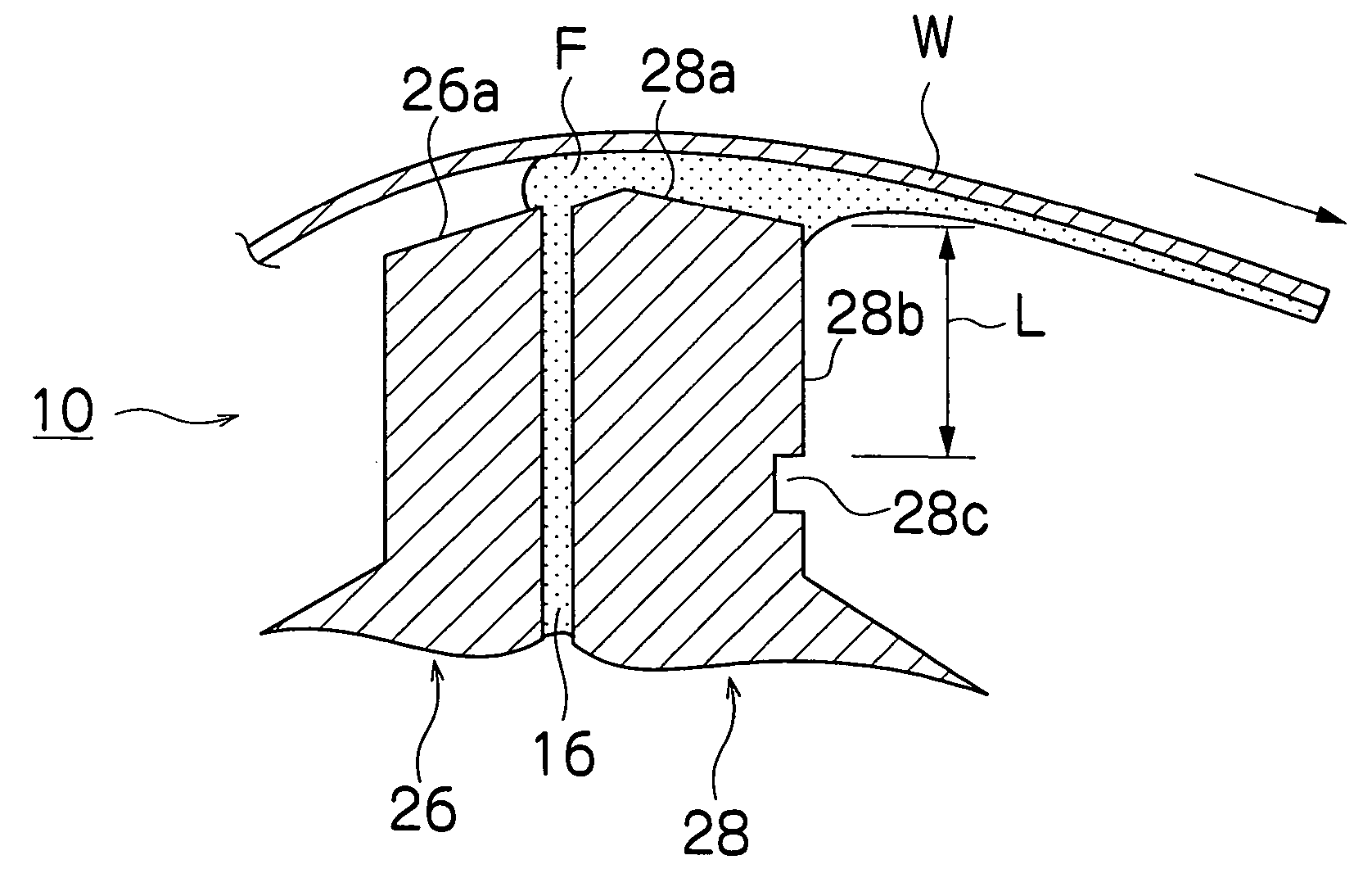
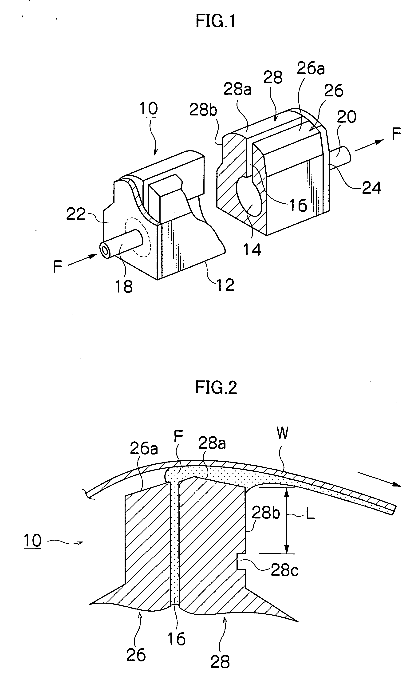
[0061] The coating fluid F prepared as the fluid A was applied to the surface of the web W by using the coating head 10 shown in FIGS. 1 and 2 and the coating film after drying was evaluated. Seven films were made with respect to different states of working on the back edge back surface 28b of the coating head 10 and were compared with each other. The surface roughness Ra of the back edge back surface 28b was changed in the range from 0.1 to 0.7 μm and the distance L (shown as “smooth portion length” in the table of FIG. 6) was changed in the range from 0.3 to 1.0 mm. The surface roughness Ra of the back edge back surface 28b was evaluated with a measuring apparatus manufactured by WYCO Corp. (model name: TOPO-3D).

[0062] As the Web W, a 60 μm thick PET (polyethylene terephthalate) member was used. The web W travel speed was set to 200 m / min. The rate of ejection of the coating fluid F was controlled so that the thickness of the layer of the coating fluid F is 5 μm in a wet conditio...

example 2

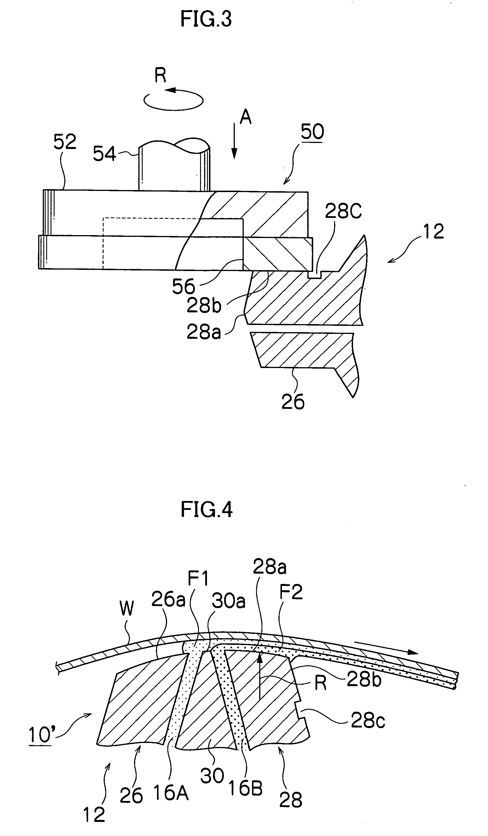
[0072] The coating fluid F1 prepared as the fluid B was applied to the surface of the web W by using the coating head 10′ shown in FIG. 4, and the coating fluid F2 prepared as the fluid A was applied on the undried coating fluid F1, and the coating film after drying was evaluated. Seven films were made with respect to different states of working on the back edge back surface 28b of the coating head 10′ and were compared with each other. The surface roughness Ra of the back edge back surface 28b was changed in the range from 0.1 to 0.7 μm and the distance L (shown as “smooth portion length” in the table of FIG. 7) was changed in the range from 0.3 to 1.0 mm. The surface roughness Ra of the back edge back surface 28b was evaluated with a measuring apparatus manufactured by WYCO Corp. (model name: TOPO-3D).

[0073] As the Web W, a 6 μm thick PEN (polyethylene naphthalate) member was used. The web travel speed was set to 500 m / min. The rates of ejection of the coating fluids F1 and F2 we...


PUM

PropertyMeasurementUnit
surface roughness Raaaaaaaaaaa
distanceaaaaaaaaaa

Abstract

The coating head according to the present invention comprises a slit facing the supporting member along a width direction of the supporting member, the coating fluid being ejected through an opening of the slit, a front edge surface provided on an upstream side of the slit in a direction of travel of the supporting member, the front edge surface facing the supporting member, a back edge surface provided on a downstream side of the slit in the direction of travel of the supporting member, the back edge surface facing the supporting member, and a back edge back surface intersecting the back edge surface by forming a predetermined angle therebetween, wherein a surface roughness Ra of the back edge back surface is 0.2 μm or less.

Description

BACKGROUND OF THE INVENTION [0001] 1. Field of the Invention [0002] The present invention relates to a coating head and a coating apparatus and, more particularly, to a coating head and a coating apparatus suitable for forming a coating film such as a magnetic recording layer on a flexible supporting member traveling while being supported by travel guide devices such as guide rollers. [0003] 2. Description of the Related Art [0004] Conventional methods for forming a coating film on a flexible supporting member traveling continuously while being supported by travel guide devices such as guide rollers include application-type methods such as roller coating, dip coating and fountain coating, and measuring-type methods such as air-knife coating, blade coating and bar coating. As methods using a combination of an application-type method and a measuring-type method in one place, extrusion coating, slide bead coating, curtain coating and so on have been used. [0005] Extrusion coating among...

Claims


Application Information

Patent Timeline
Patent Type & Authority Applications(United States)
IPC IPC(8): B05C3/18B05C1/00B05C5/02B05C9/06B05D3/12G11B5/842
CPCB05C9/06B05C5/0254
Inventor TOMARU, MIKIO
Owner FUJIFILM CORP
Why Eureka
Try Eureka