

Device for cutting up foodstuffs
a technology for food processors and devices, applied in applications, manufacturing tools, grain treatment, etc., can solve the problems of uneven processing, unfavorable catching of items, and power loss of food processors, so as to prevent extensive catching, reduce thermal stress, and prevent large catching
- Summary
- Abstract
- Description
- Claims
- Application Information
AI Technical Summary
Benefits of technology
Problems solved by technology
Method used
Image

Examples
Embodiment Construction
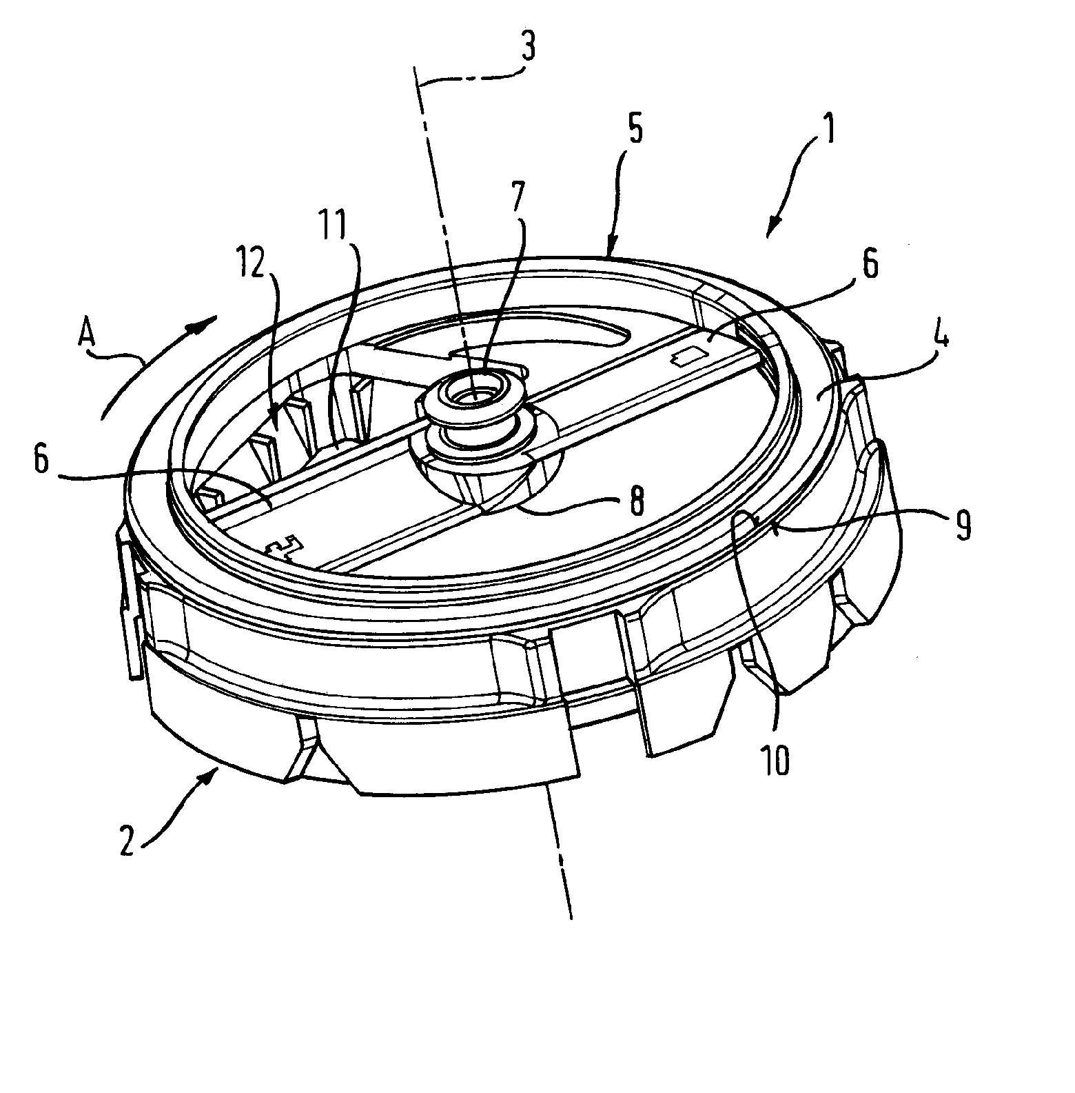
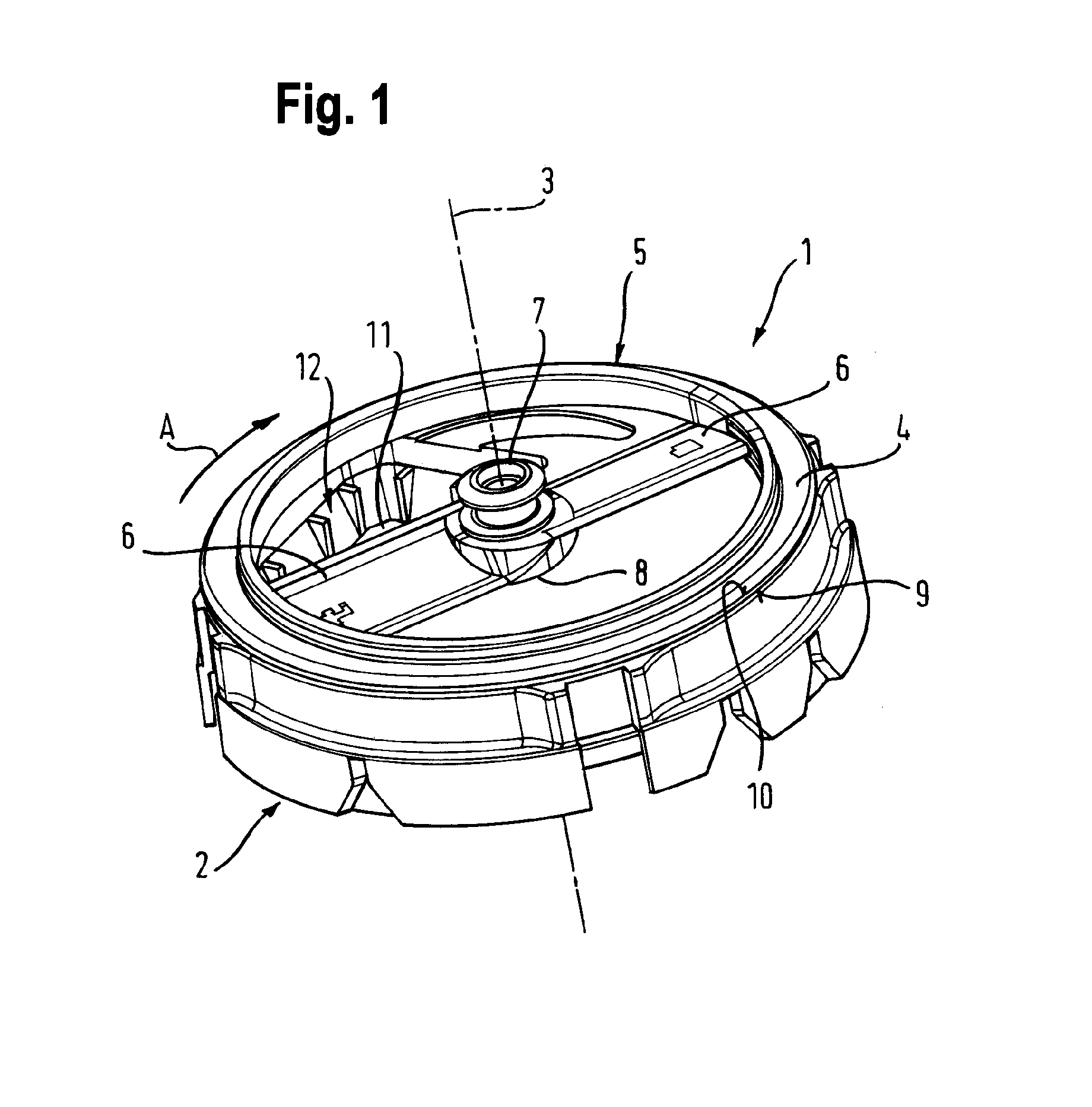
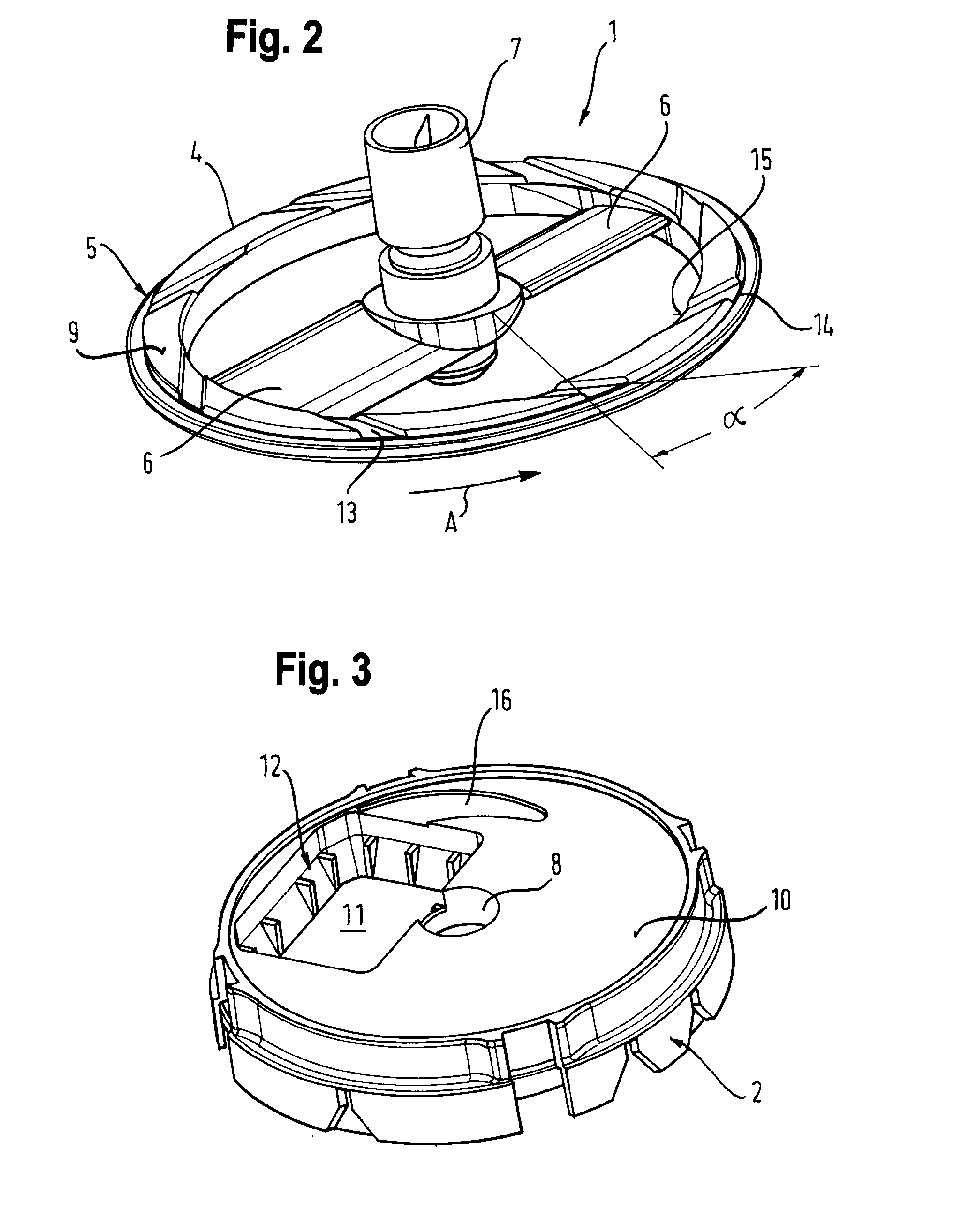
[0013]Advantageous configurations or developments, which can be utilized individually or in combination with one another, are the subject matter of the dependent claims.
[0014]The apparatus is preferably provided to chop items to be processed, in particular to dice foodstuffs, the rotating ring element being configured as a blade support for cutting blades rotating about a rotation axis along a cutting grid and the housing part accommodating a cutting grid and having an axial opening in the region of the cutting grid. When chopping sticky foodstuffs, e.g. foodstuffs with a high sugar and / or water content, such apparatuses tend to catch items in a particular manner, so that the inventive advantages have a greater effect. Taste impairment due to thermal decomposition or oxidation can also be reduced.
[0015]The means for the radial conveying of the items being processed are advantageously provided in the direction of the rotation axis of the rotating ring element, where they can be guide...
PUM
 Abstract
Description
Claims
Application Information