Device for cooling hot gas to be discharged from an aircraft

a technology for hot gas discharge and aircraft, which is applied in the direction of rocket engine plants, machines/engines, light and heating apparatus, etc. it can solve the problems of air being sucked in from the external environment, not achieving effective thermal structure protection, and the aircraft cannot be located or identified by means of thermal signature, so as to reduce the flow noise and thus the noise, the effect of reducing the flow nois

Inactive Publication Date: 2013-02-12
AIRBUS OPERATIONS GMBH
View PDF17 Cites 8 Cited by
  • Summary
  • Abstract
  • Description
  • Claims
  • Application Information

AI Technical Summary

Benefits of technology

[0014]Between overlapping pipe ends of pipe sections, there is provided at least one annular gap, into which cooling air is sucked by negative pressure when hot gas flows through. The use of annular gaps results in the side effect that the outflow noise of the hot gas can be reduced through lowering of the flow velocity of the hot gas. The overlapping of pipe ends gives rise to an increasing diameter of the duct through which hot gas flows. This means that a markedly larger flow cross-section is present at the outlet point of the duct than at the inlet point. As a result, the flow velocity of the hot gas also with additional cooling air at the outlet point is markedly lowered, thereby reducing the flow sounds and thus the noise. An additional side effect of the annular gaps is the possibility of compensation for relative movements, structural deformations, thermal stresses and assembly and manufacturing tolerances of the hot gas source. An annular gap facing the outlet point is partially closed in order to form on the outlet side a protective underflow layer from the discharged cooling air.
[0015]The device according to the invention has a number of advantages over known devices from the prior art. The hot gas to be discharged is cooled by mixing with cooling air, so that the hot gas emerging does not excessively heat up the surrounding structure or the outer skin of the aircraft. As a result, the thermal signature is also less pronounced than in the prior art. When the device according to the invention is used as an APU exhaust gas system, a higher strength of the components is achieved, since the temperature in the interior of the exhaust gas system is reduced by the cooling air from the cooling air sources and causes less thermal stress.
[0016]Firstly, through the cooling of the hot gas, weight and costs can be reduced by saving temperature-resistant material, such as, for example, steel, titanium or temperature-resistant plastics, for protecting the structure surface around the hot gas outlet opening. On the other hand, the region, influenced by the heat input, around the hot gas outlet is kept small, so that the thermal signature is weakened and the location of the aircraft is made more difficult or prevented. In addition, insulating material and thus weight can be saved, since the aircraft structure in the interior of the aircraft is markedly less subjected to heat by the comparatively cool exhaust gas system.
[0017]The device according to the invention has several particularly advantageous developments. In particular, by using exhaust air from other aircraft systems—e.g. exhaust air of an APU oil cooler—the number of separate outlets for exhaust air from the aircraft outer skin are reduced. Furthermore, the oil cooler exhaust air flow additionally cools the surface temperature of the exhaust gas system as a whole and results in less impairment of the aircraft structure surrounding the exhaust gas system.

Problems solved by technology

Furthermore, particularly in the case of military aircraft, there is the requirement to make the thermal signature of an aircraft as weak as possible, so that the aircraft cannot be located or identified by means of the thermal signature.
With this technical solution, the exhaust gas of the APU flowing out of the tail cone produces, owing to the jet pump effect, a negative pressure which results in air being sucked in from the external environment.
However, this technical solution does not achieve a very effective thermal structure protection.
Moreover, the power of the APU is reduced, since only very little cooling effect is achieved particularly when starting up and shutting down the APU, and the APU cannot be operated optimally.
The disadvantage of air guide plates on the outer contour, however, is the increase in drag of the aircraft and thus in the direct operating costs.

Method used


Image

  • Device for cooling hot gas to be discharged from an aircraft
  • Device for cooling hot gas to be discharged from an aircraft
  • Device for cooling hot gas to be discharged from an aircraft

Examples


Embodiment Construction

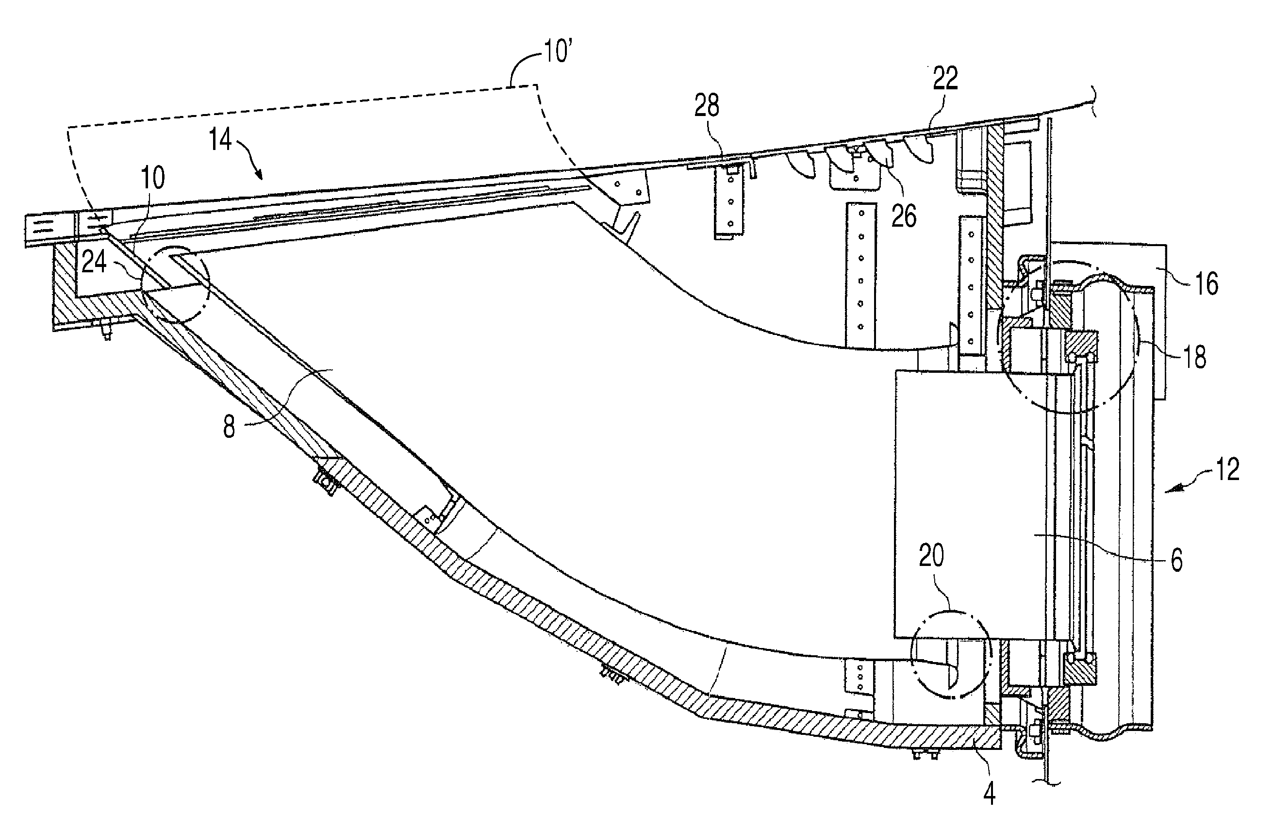
[0022]For a better understanding, various embodiments of the device according to the invention, which are integrated by way of example into a military transport aircraft of the type AIRBUS A400M, are described below. The device according to the invention is not limited to the cooling of APU exhaust gases, but can also cool other hot gases from other systems, such as, for example, from a fuel cell. The general term “hot gas” is therefore used below in some cases. The turbine exhaust gas of the APU is to be regarded as a special form of a hot gas.

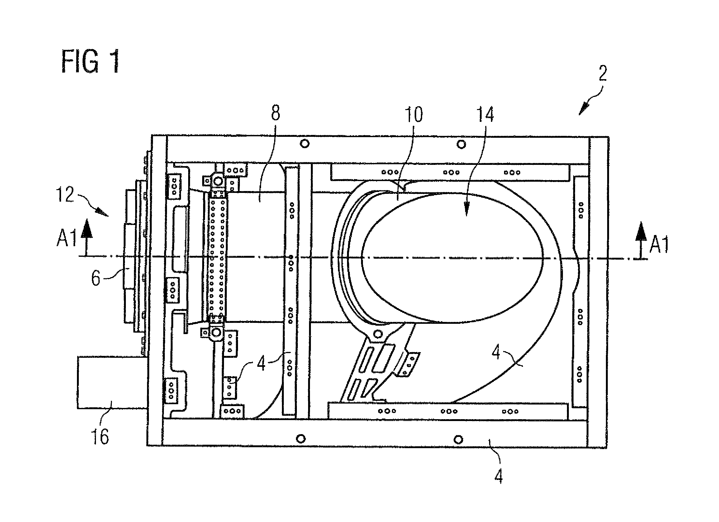
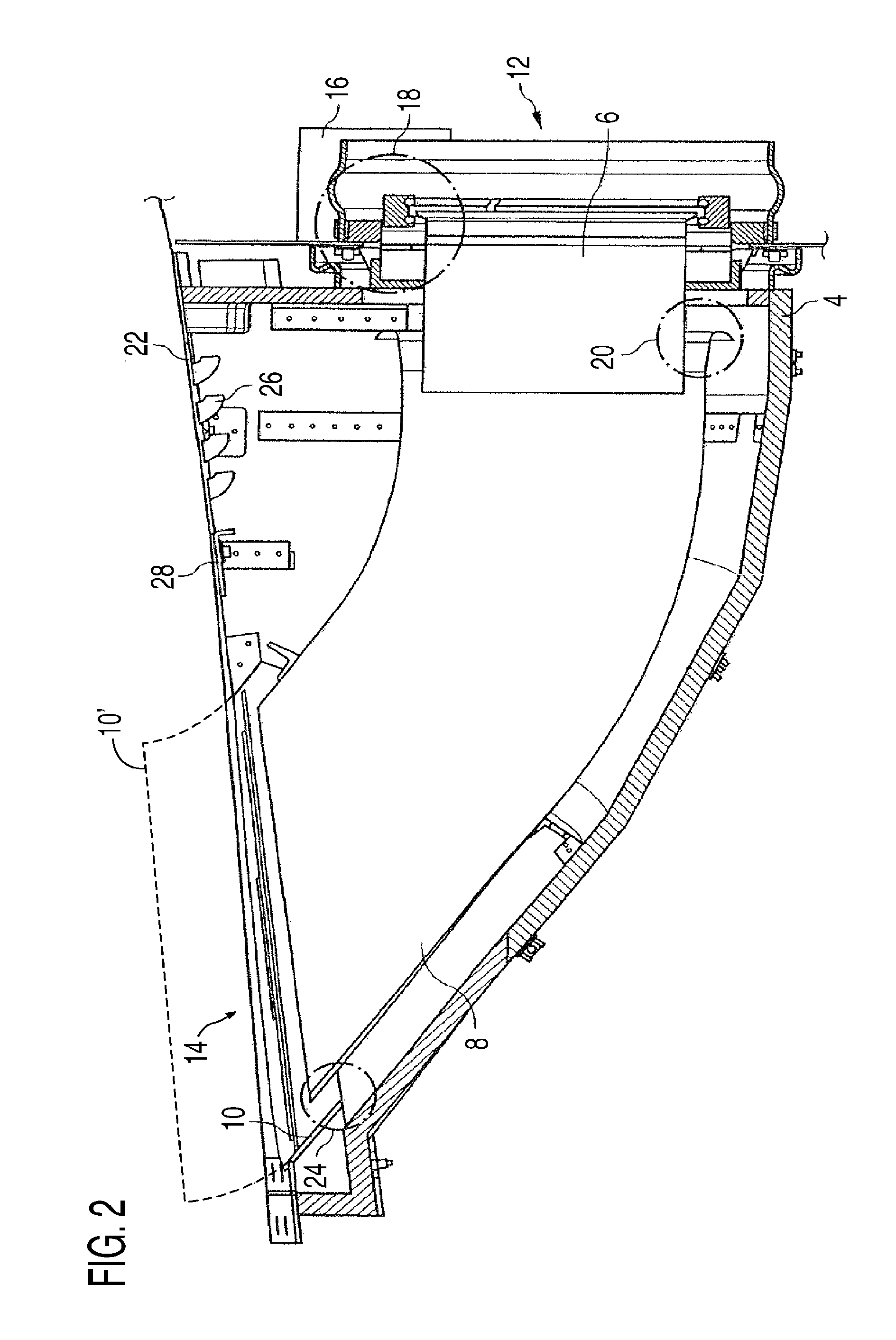
[0023]FIG. 1 shows an exhaust gas system 2, in which a housing covering fitted during operation has been removed for better illustration. The exhaust gas system 2 comprises a housing 4 formed from a sheet-metal trough, reinforcing components, holders and fittings, and an exhaust gas duct consisting of three successive exhaust gas pipes 6, 8 and 10 and extending from an exhaust gas inlet point 12 into the housing 4. The exhaust gas pipe 6 lead...


PUM


Abstract

A device for cooling hot gas to be discharged from an aircraft includes a duct for leading the hot gas from a hot gas source which is connectable to the device to an outlet point, and a frame which surrounds the duct and serves for mounting the duct. The duct is formed from one or more pipe sections and has one or more cooling air inlet points which is connectable to one or more cooling air sources in order to mix the hot gas with cooling air. An outlet pipe section of the duct extends outwards beyond the aircraft outer skin to lead hot gas through and out of a flow boundary layer on the outer skin.

Description

[0001]This application claims priority to PCT Application No. PCT / EP2008 / 009946 filed on Nov. 24, 2008, which claims priority to U.S. Provisional Patent Application. No. 61 / 015,882 and to German Patent Application No. 1020070061994.6, both filed on Dec. 21, 2007TECHNICAL FIELD[0002]The invention relates to a device for cooling hot gas to be discharged from an aircraft.BACKGROUND[0003]Hot gas to be discharged from an aircraft results, for example, from the operation of an auxiliary power unit (also referred to as “APU” below) which produces hot gas in the form of exhaust gas at a temperature of up to 730° C. Hot gas produced in an APU should be discharged as cold as possible into the environment in order to keep stresses in the structure and / or the outer skin of the aircraft as a result of local temperature peaks as low as possible. Furthermore, particularly in the case of military aircraft, there is the requirement to make the thermal signature of an aircraft as weak as possible, so...

Claims


Application Information

Patent Timeline
Patent Type & Authority Patents(United States)
IPC IPC(8): A01K1/10
CPCB01F5/0471B01F5/049B64D41/00B01F5/0413Y02T50/44B64D2033/045B64D2041/002Y02T50/40B01F25/31432B01F25/314B01F25/312
Inventor PIESKER, MARKUS
Owner AIRBUS OPERATIONS GMBH
Why Eureka
Try Eureka