
Flow Regulator

Active Publication Date: 2008-05-22
NEOPERL
View PDF13 Cites 6 Cited by
  • Summary
  • Abstract
  • Description
  • Claims
  • Application Information

AI Technical Summary

Benefits of technology

[0009]A substantial advantage of the invention lies in the defined stress on the elastic spring element in one effective direction. In one advantageous execution model, the elastic spring element is stressed, for example, exclusively by means of a pressure force in the direction of the flow of the fluid via the throttle cap. In that case, no distension takes place on the elastic spring element nor on the throttle cap lying in the fluid stream.
[0010]Preferably, the elastic spring element is arranged outside of at least the one flow duct. In this execution model, the mechanically stressed elastic spring element is located outside of the fluid flow and is therefore exposed to clearly less thermal stress, especially in the case of hot fluids. The arrangement outside of the fluid flow also protects the elastic spring element from calcification and thus substantially increases the life of the flow regulator.
[0011]A distributor dome around which several flow ducts are circularly arranged may be formed centrically in the insertion member. In that case, the control gap may be formed by the distributor dome and the throttle cap. The distributor dome may have a shape corresponding to a cone, a truncated cone, a sphere, a hemisphere, a sphere segment or, respectively, a rotation paraboloid or an ellipsoid. The advantage of the sphere shape or a shape with a rounded surface vis-à-vis the cone shape lies in a larger surface of the distributor dome that is wetted by the fluid, which results in a greater force acting on the elastic spring element via the throttle cap.
[0012]Providing an inlet aperture for the fluid located centrically in the throttle cap proved to be particularly advantageous. Through this, the fluid entering the flow regulator is distributed evenly and the throttle cap is moved uniformly in a radial direction towards the insertion member or the distributor cap, without canting.
[0013]It is advantageous if the throttle cap is arranged in the flow direction before the insertion member. Then, the predominant portion of the throttle cap as well as the inlet aperture will be located in an axial direction outside of the insertion member. By way of this design, the insertion member can be made particularly short in its axial direction.BRIEF DESCRIPTION OF THE SEVERAL VIEWS OF THE DRAWING(S)

Problems solved by technology

With increasing flow velocity of the fluid, the throttle cap is brought closer to the insertion member via the elastic spring element, resulting in a reduction of the effective cross section.

Method used


Image

  • Flow Regulator
  • Flow Regulator
  • Flow Regulator

Examples


Embodiment Construction

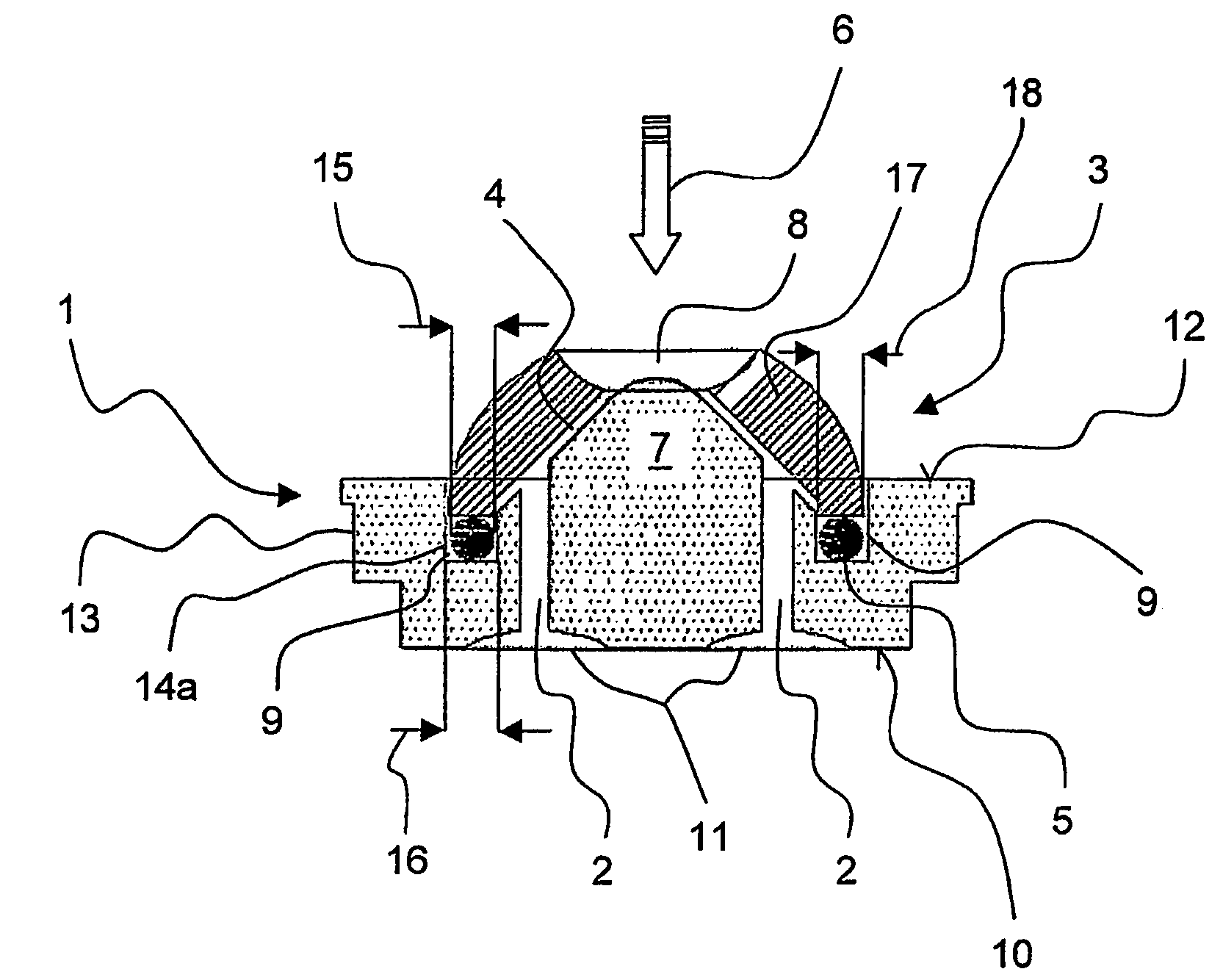
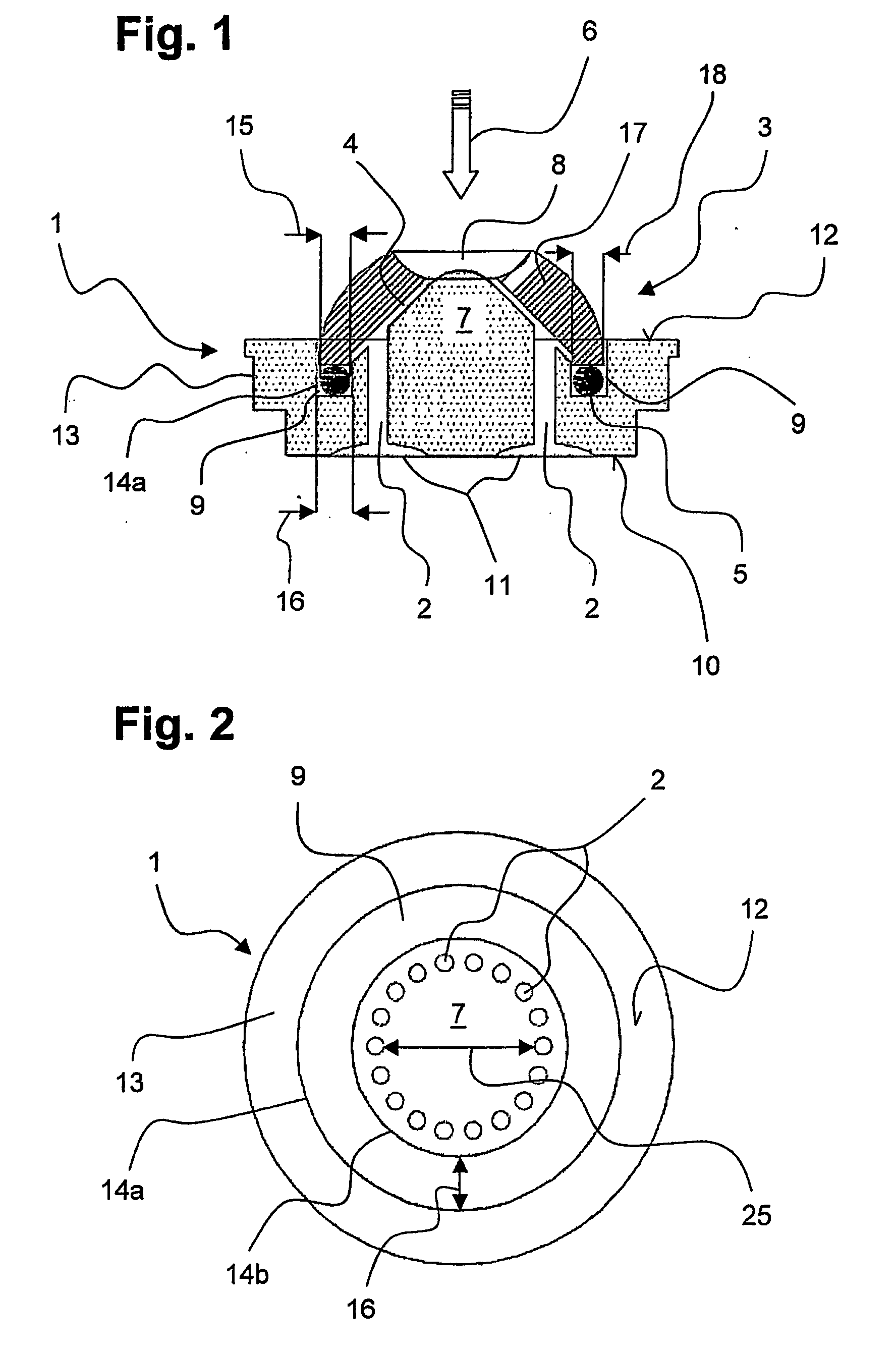
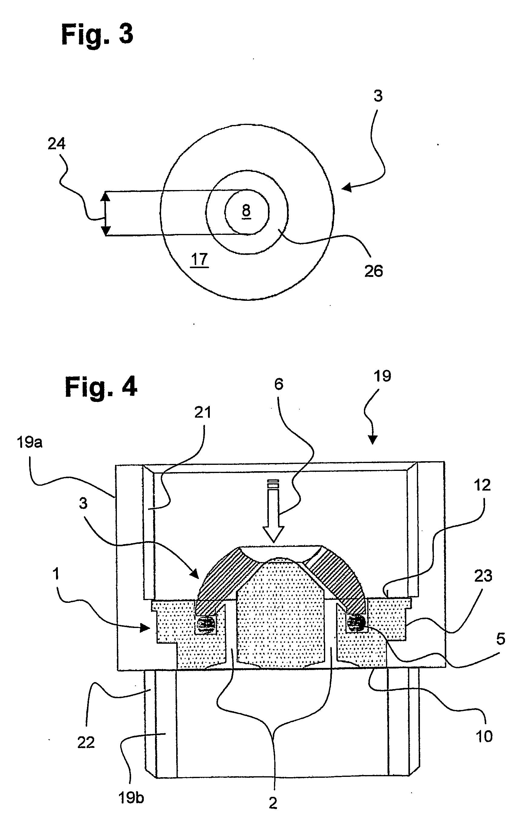
[0020]FIG. 1 shows a cross section of a flow regulator with an insertion member 1 and a throttle cap 3 designed as a throttle element. In an installed state, a fluid, not shown, passes through the flow regulator in the direction of the flow 6.

[0021]The insertion member has a circumferential edge section 13 that closes with a level surface on one inlet side 12 facing the flow direction 6. On the side facing away from the flow direction 6, the insertion member 1 is formed with an even outlet side 10 that is parallel to the inlet side 12.

[0022]In a central area, a distributor dome 7 that tapers towards the flow direction 6 is arranged on the insertion member 1 that protrudes vis-a-vis the edge section 13. In a section lying below the inlet side 12 a multitude of flow ducts 2 are arranged in the distributor dome 7 in wreath-like fashion, of which the representation of FIG. 2 shows only 2 flow ducts 2 lying opposite each other. The flow ducts 2 run through the insertion member all the wa...


PUM


Abstract

Disclosed is a flow regulator, especially for insertion into a jet regulator in an outlet fixture, comprising an insertion member that is penetrated by at least one flow duct in an axial direction as well as a throttle element which forms a control gap along with the insertion member in order to allow a fluid to penetrate into the at least one flow duct. The aim of the invention is to create a flow regulator which allows for significantly greater durability during use while offering maximum ease of operation when fluid is discharged. Said aim is achieved by a flow regulator in which the throttle element is embodied as a dimensionally stable throttle cap that is supported in relation to the insertion member via an elastic spring element.

Description

BACKGROUND OF THE INVENTION[0001]1. Field of the Invention[0002]The invention relates to a flow regulator, in particular for insertion in a jet regulator in an outlet fitting, with an insertion member that is penetrated in an axial direction by at least one flow duct, and a throttle element that, together with the insertion member, forms a control gap for the passage of a fluid into the at least one flow duct.[0003]2. Description of Related Art[0004]Such a flow regulator or constant flow holding device is disclosed for example in DE 102 20 287 A1. The known flow regulator features a regulator casing with a centrically arranged fastening post and a flow channel surrounding the latter. In the flow channel there is a throttle body made of an elastic material, with the throttle body being slid onto the fastening post which it encircles. A fluid flowing through the flow regulator deforms the throttle body due to a pressure differential generated by the flow through which reduces the free...

Claims


Application Information

Patent Timeline
IPC IPC(8): F16K31/126F16K21/00
CPCG05D7/0133G05D7/012Y10T137/777Y10T137/7869
Inventor RUHNKE, CHRISTOF
Owner NEOPERL
Learn More