
Coil device

a coil device and coil technology, applied in the direction of transformer/inductance details, inductances with magnetic cores, inductances, etc., can solve the problems of easy change of characteristics, such as inductance, and achieve the improvement of the flow of magnetic lines, the stability of temperature change characteristics, and the strength of the coil device for the mount board.

Pending Publication Date: 2021-09-02
TDK CORPARATION
View PDF6 Cites 2 Cited by
  • Summary
  • Abstract
  • Description
  • Claims
  • Application Information

AI Technical Summary

Benefits of technology

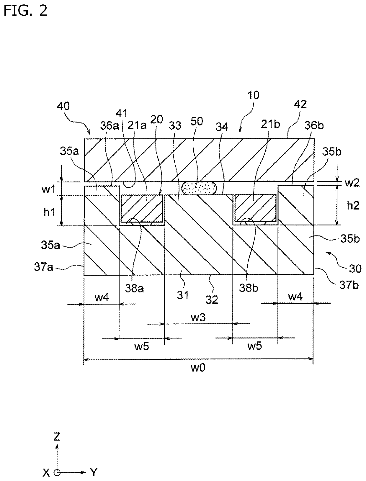
The present invention is a coil device that can achieve a high inductance, even when using a core with metal magnetic material. The device has a specific gap between the middle leg and the sub core, which is wider than the gap between the outer leg and the sub core. This configuration improves the flow of magnetic lines and enhances the performance of the inductor. The middle leg should be at least 1.5-2.5 times as wide as the outer leg for optimal results.

Problems solved by technology

However, an inductor with a core made of ferrite material has a problem that characteristics, such as inductance, change easily by temperature change.
However, there is a problem that an inductor with a core including a metal magnetic material or so normally has a small inductance.

Method used


Image

  • Coil device
  • Coil device
  • Coil device

Examples


example 1

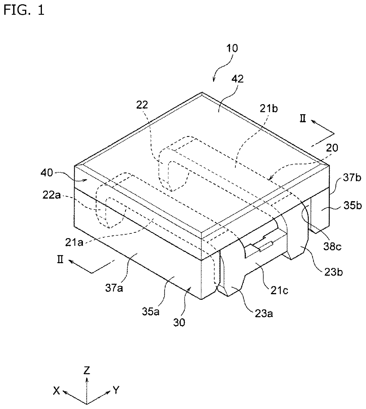
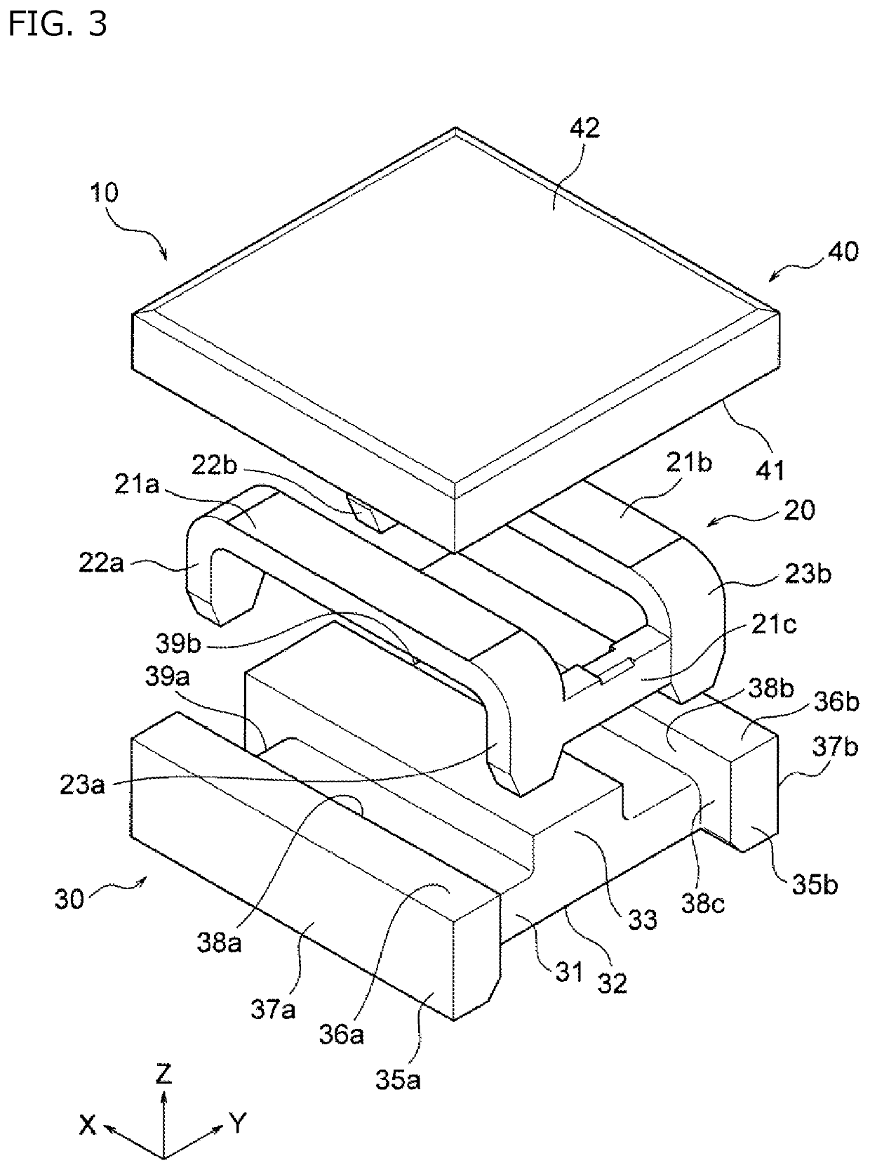
[0082]Samples of the coil device 10 shown in FIG. 1 to FIG. 3 were manufactured. The samples of the coil device 10 were measured in terms of inductance with the following conditions.

[0083]A center gap w1 of the coil device 10 according to the present embodiment was changed as shown in the horizontal axis of FIG. 4, and an inductance L of each sample of the coil device 10 was measured with an impedance analyzer. The results are shown in FIG. 4.

[0084]As shown in FIG. 4, it turned out that the inductance decreased if the center gap w1 became slightly larger than zero, but started to increase after about 10 μm. Then, it turned out that the inductance after the center gap w1 was 15 μm to 20 μm was higher than that when the center gap w1 was zero. It turned out that the inductance to be obtained increased as the center gap w1 further increased and became lower than that when the center gap w1 was zero after the center gap w1 exceeded 55 μm.


PUM

PropertyMeasurementUnit
widthaaaaaaaaaa
temperatureaaaaaaaaaa
widthaaaaaaaaaa

Abstract

A coil device includes a main core and a sub core. The main core includes a middle leg for winding a coil body and an outer leg connected with the middle leg via a base portion. The sub core is disposed to face the base portion across the middle leg. A gap between the middle leg and the sub core is wider than that between the outer leg and the sub core.

Description

BACKGROUND OF THE INVENTION[0001]The present invention relates to a coil device used as, for example, an inductor.[0002]A coil device used as an inductor is used for various electronic circuits, such as DC-DC converters. As such an inductor, for example, the inductor shown in Patent Document 1 is known.[0003]In conventional inductors, a core made of ferrite material is normally used to improve the inductance. However, an inductor with a core made of ferrite material has a problem that characteristics, such as inductance, change easily by temperature change. In particular, there has recently been a demand for an inductor whose characteristics do not change very much even at a high temperature of about 100-170° C.[0004]Then, an inductor with a core whose characteristics (e.g., inductance) do not change very much by temperature change, such as a core including a metal magnetic material, has been studied. However, there is a problem that an inductor with a core including a metal magneti...

Claims


Application Information

Patent Timeline
Patent Type & Authority Applications(United States)
IPC IPC(8): H01F27/24H01F27/29H01F41/04
CPCH01F27/24H01F41/04H01F27/29H01F37/00H01F3/14H01F27/2852H01F17/04H01F27/292H01F27/263
Inventor ASHIZAWA, SYUNBANZAI, TAKAHIROUMEKI, RIKUSUGIMOTO, SATOSHISASAKI, HITOSHI
Owner TDK CORPARATION
Learn More