

Installation structure for coolant pipe
A refrigerant and pipeline technology, which is applied in the field of installation structure of refrigerant pipelines, can solve the problem of reduced installation strength of refrigerant pipelines, insufficient reduction of thermal resistance of refrigerant pipelines and heat transfer components, insufficient pushing pressure of refrigerant pipelines, etc. problems, to achieve the effect of ensuring installation strength, ensuring cooling performance, and uniform pushing force
- Summary
- Abstract
- Description
- Claims
- Application Information
AI Technical Summary
Problems solved by technology
Method used
Image

Examples
no. 1 approach
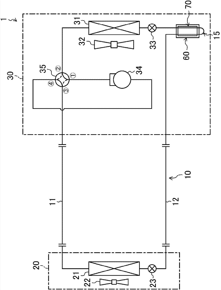
[0065] An embodiment according to the present invention is an air conditioner 1 that has a refrigerant circuit 10 and switches between a cooling operation and a heating operation. The air conditioner 1 has an indoor unit 20 installed indoors and an outdoor unit 30 installed outdoors. The indoor unit 20 and the outdoor unit 30 are connected to each other through two connecting pipes 11 and 12 to form a closed refrigerant circuit 10 . Refrigerant circuit 10 is filled with refrigerant. A vapor compression refrigeration cycle is performed by refrigerant circulation in the refrigerant circuit 10 .
[0066] 〈Indoor unit〉
[0067] The indoor unit 20 has an indoor heat exchanger 21 , an indoor fan 22 and an indoor expansion valve 23 . The indoor heat exchanger 21 is constituted by, for example, a transverse-fin fin-and-tube heat exchanger. In the indoor heat exchanger 21 , the refrigerant flowing inside the heat transfer tubes exchanges heat with the air sent by the indoor fan 22 ...
no. 2 approach
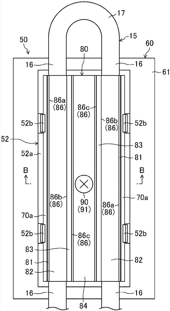
[0108] In the air conditioner 1 according to the second embodiment of the present invention, the attachment structure 50 of the cooling pipe 15 is different from the above-mentioned embodiment. Below, refer to Figure 5 to Figure 9 Differences from the first embodiment described above will be described.
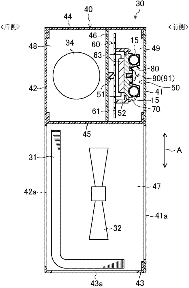
[0109] Such as Figure 5 As shown, in the air conditioner 1 of the second embodiment, the power conversion device 60 is disposed on the side facing the front panel 41 , and the cooling pipe 15 is disposed on the rear side of the power conversion device 60 .
[0110] In the power conversion device 60 , the printed circuit board 61 is provided on the rear side of the front plate 41 , and the power element 63 is provided on the rear side of the printed circuit board 61 . The printed circuit board 61 is fixed to the cabinet 40 via the supporting member 51 . The supporting part 51 is mounted on, for example, the top plate of the casing 40 or other parts, so that the front plate...
no. 3 approach
[0127] The air conditioner 1 according to the third embodiment of the present invention is different from the above-mentioned embodiment in the structure of the mounting structure 50 of the cooling pipe 15 . Refer below Figure 10 ~ Figure 13 Differences from the second embodiment will be described.
[0128] The fitting groove 100 of the refrigerant jacket 70 in the third embodiment penetrates the refrigerant jacket 70 in the thickness direction of the refrigerant jacket 70 . A fitting groove 100 is formed at a central position of the middle portion 74 . The fitting groove 100 has a pair of key grooves 104 formed on the surface side of the refrigerant jacket 70 (the leaf spring member 80 side) and a cylindrical groove 105 formed on the inner side of the key grooves 104 .
[0129] The pressing mechanism 90 in the third embodiment is constituted by a lever type fixing member 120 . The lever-type fixing member 120 has a cylindrical rod portion 121 , a lever portion 122 that sw...
PUM
 Abstract
Description
Claims
Application Information