
Radio-frequency circuit module and radio communication apparatus

a radio communication apparatus and radio frequency technology, applied in the direction of casings/cabinets/drawers, casings/cabinets/drawers details, printed circuit non-printed electric components association, etc., can solve the problems of difficult miniaturization, difficult to design a module whose chip size is close to the size of the ic,

Inactive Publication Date: 2005-12-08
TAIYO YUDEN KK
View PDF2 Cites 18 Cited by
  • Summary
  • Abstract
  • Description
  • Claims
  • Application Information

AI Technical Summary

Benefits of technology

[0011] Accordingly, in an aspect, it is an object of the present invention to provide an effective procedure for miniaturizing an RF circuit module including an RF circuit and a crystal oscillator circuit.
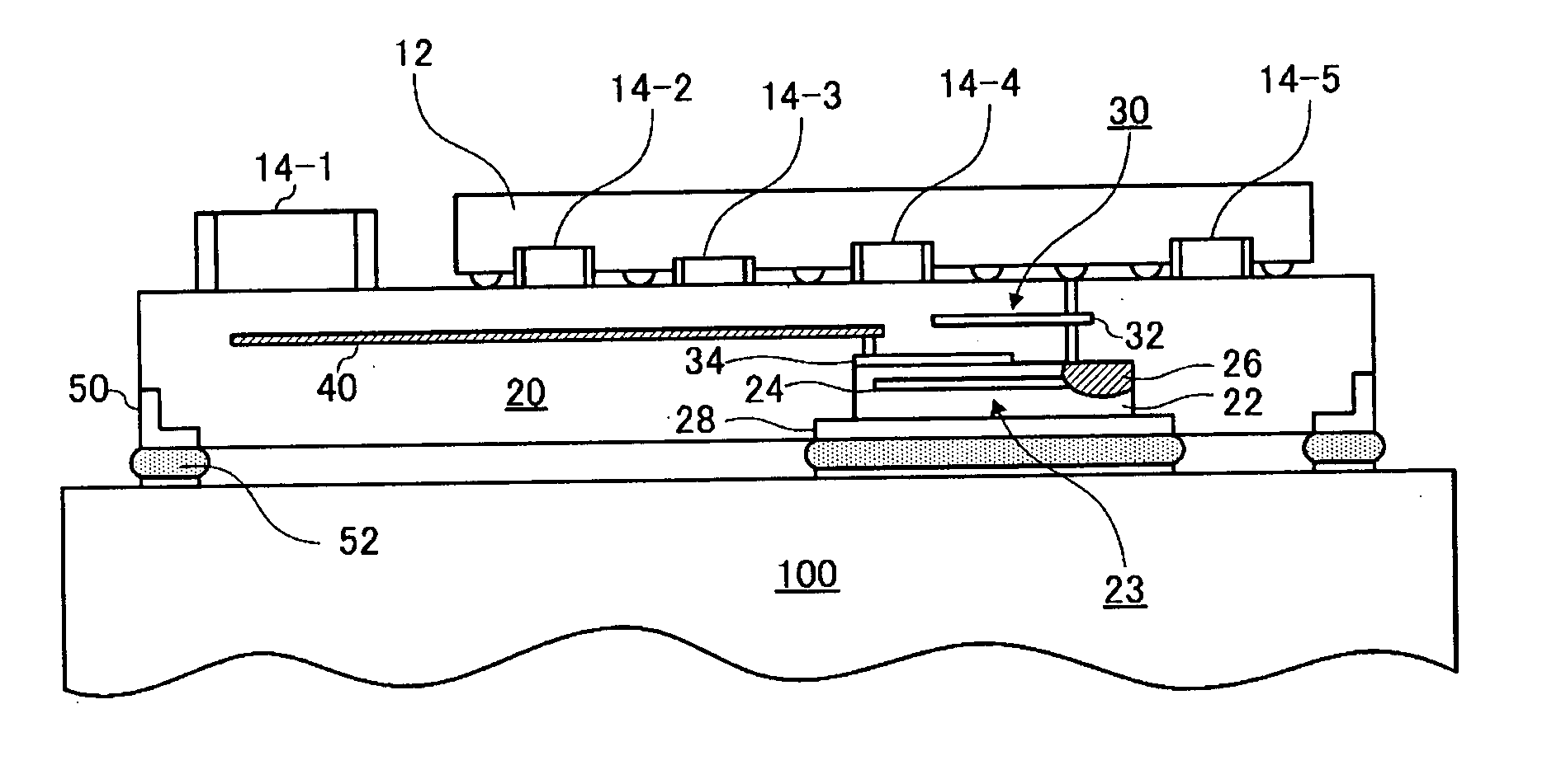
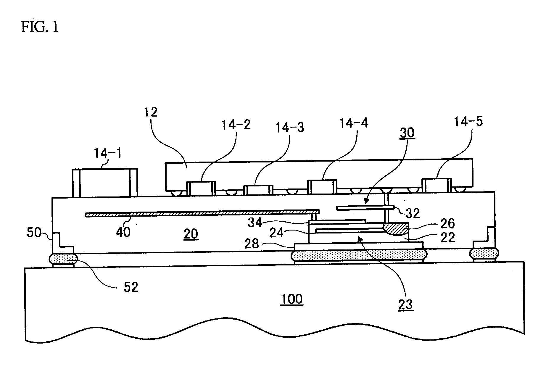
[0019] According to the above aspect, by integrating an adjusting section of a crystal-oscillator circuit into an RF IC disposed on the front face of a multilayer substrate and by accommodating a crystal oscillator in a cavity provided in the rear face of the multilayer substrate, the crystal-oscillator circuit using the IC can be adjusted and the mounting area can be reduced.
[0020] In an embodiment, a signal processing section of the RF circuit is a circuit block that performs signal processing using a clock signal generated by the crystal-oscillator circuit. By integrating the signal processing section of the RF circuit with part of the crystal-oscillator circuit, the length of wiring between the RF circuit and the crystal-oscillator circuit can be reduced. Thus, a circuit module with excellent oscillation characteristics and reduced noise can be realized. It is preferable that an inverting amplifier of the crystal-oscillator circuit be integrated into the same IC.
[0023] According to this aspect, since a cavity accommodating a crystal oscillator and a cavity accommodating a memory element are provided separately, a crystal oscillator can be easily sealed and a rear region of a multilayer substrate can be effectively used. Thus, miniaturization equivalent to an RF IC, which may be the largest element, can be expected. In an embodiment, since the RF IC in which an RF front end part and a baseband part are integrated is larger than the area necessary for sealing the crystal oscillator and for accommodating an EEPROM, a structure in which the RF IC is disposed on the front face of the multilayer substrate and in which the crystal oscillator and the memory element are disposed on the rear face of the multilayer substrate is effective.
[0028] As described above, in one or more embodiments, since a sealing cap for sealing a crystal oscillator is made of a conductive material and the sealing cap is exposed on the rear face of a multilayer substrate, the sealing cap can be used as a reinforcing terminal or a ground pattern. Thus, the area in which the crystal is installed can be effectively used. Preferably, the sealing cap is made of an alloy of gold and tin.
[0030] As described above, in one or more embodiments, since the circuit module and the motherboard are connected to each other with the sealing cap therebetween, the mounting strength of the circuit module increases. In addition, when the sealing cap is used as a ground pattern, reinforcement of the ground pattern can be achieved.

Problems solved by technology

In this structure, since the crystal oscillator and the IC are accommodated in the same cavity, a certain mounting area is required, and it is thus difficult to design a module whose size is close to the chip size of the IC.
When taking into consideration the fact that single-chip ICs in which an RF circuit block and a baseband circuit block are integrated with each other have been considered and that modules whose size is equivalent to the size of IC chips have been desired in recent years, it is difficult to realize miniaturization with the structures described in Japanese Unexamined Patent Application Publication Nos. 10-135756 and 2002-9225.

Method used


Image

  • Radio-frequency circuit module and radio communication apparatus
  • Radio-frequency circuit module and radio communication apparatus
  • Radio-frequency circuit module and radio communication apparatus

Examples


Embodiment Construction

[0041] An RF circuit module according to embodiments of the present invention will be described with reference to the drawings. The present invention is not limited to the following embodiments, and various changes and modifications can be made to the present invention without departing from the spirit and scope thereof.

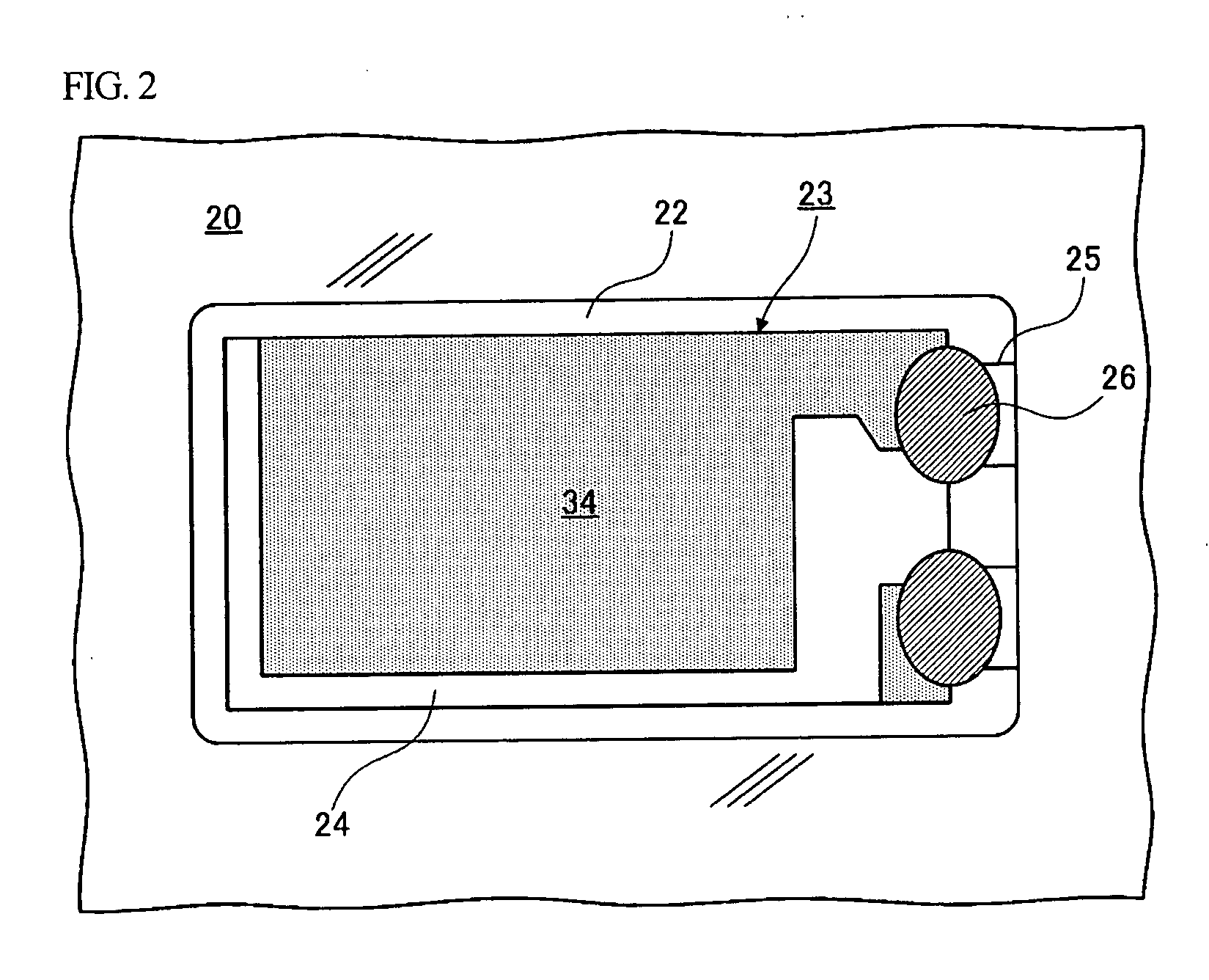
[0042]FIG. 1 is a cross-sectional view showing the structure of an RF circuit module according to a first embodiment of the present invention. Referring to FIG. 1, in the circuit module, an IC element 12 and passive components 14-1 to 14-5 are disposed on the front face of a multilayer substrate 20, an inner capacitor 30 is disposed on an inner layer of the multilayer substrate 20, and a cavity 22 is provided in the rear face of the multilayer substrate 20. A crystal strip 24 is fixed in the cavity 22 using an electroconductive adhesive 26. The fixed crystal strip 24 constitutes a crystal oscillator 23.

[0043] The IC element 12 is a flip-chip IC in which an RF front...


PUM


Abstract

An integrated-circuit element and passive components are mounted on a front face of a multilayer substrate. A capacitor constituting a crystal-oscillator circuit is disposed inside the multilayer substrate. A cavity is provided in a rear face of the multilayer substrate. A crystal oscillator constituting the crystal-oscillator circuit is accommodated in the cavity, and the cavity is sealed with a sealing cap made of a conductive material. The sealing cap is fixed to an electrode pad provided on a motherboard with solder therebetween.

Description

BACKGROUND OF THE INVENTION [0001] 1. Field of the Invention [0002] The present invention generally relates to radio-frequency (RF) circuit modules and radio communication apparatuses, and more particularly, to an RF circuit module and a radio communication apparatus that can be miniaturized. [0003] 2. Description of the Related Art [0004] In order to reduce the size of radio communication apparatuses, RF circuit modules in which an RF front end part and a baseband part of a radio communication circuit are modularized have been considered. Such RF circuit modules are designed based on a communication standard, such as Bluetooth™ or a wireless local-area network (LAN), and incorporated into application apparatuses, such as cellular phones or personal computers, to function as modules for providing a radio communication function to the application apparatuses. [0005] From among the RF circuit modules of this type, RF circuit modules in which an RF circuit is integrated with a crystal-...

Claims


Application Information

Patent Timeline
IPC IPC(8): H01L25/04H01L25/18H01L23/12H05K1/02H01L25/00H05K1/18H05K1/00H03B5/36
CPCH03B5/36H05K1/0243H05K1/0298H05K1/183H05K2201/10075H01L2224/16H01L2924/19105F16K11/07F16K31/0613F16K31/0675
Inventor MURATA, RYUJI
Owner TAIYO YUDEN KK
Learn More