Liquid supply apparatus

a technology of liquid supply apparatus and liquid supply device, which is applied in the direction of liquid transfer device, process and machine control, instruments, etc., can solve the problem that patients should not be able to adjust the injection quantity of medicine, and achieve the effect of reducing the possibility of inferiority, convenient portability of the apparatus, and reducing the possibility of medicine injection quantity per unit tim

Inactive Publication Date: 2005-03-17
E WHA FRESENIUS KABI
View PDF20 Cites 2 Cited by
  • Summary
  • Abstract
  • Description
  • Claims
  • Application Information

AI Technical Summary

Benefits of technology

[0010] Therefore, various functions are required when the liquid supply apparatus is especially used for the medicine injection apparatus. First of all, the function of maintaining a constant medicine injection quantity per unit time is required. It is preferred that variation of the medicine injection quantity per unit time be minimized. Portability makes the apparatus convenient. Further, it is preferred that the medicine injection apparatus be constructed to have low possibility of inferiority occurrence in the parts.

Problems solved by technology

Further, the patient should not be able to adjust the injection quantity of the medicine.

Method used


Image

  • Liquid supply apparatus
  • Liquid supply apparatus
  • Liquid supply apparatus

Examples


Embodiment Construction

[0038] Hereinafter, preferred embodiments of the present invention will be explained in detail with reference to the drawings.

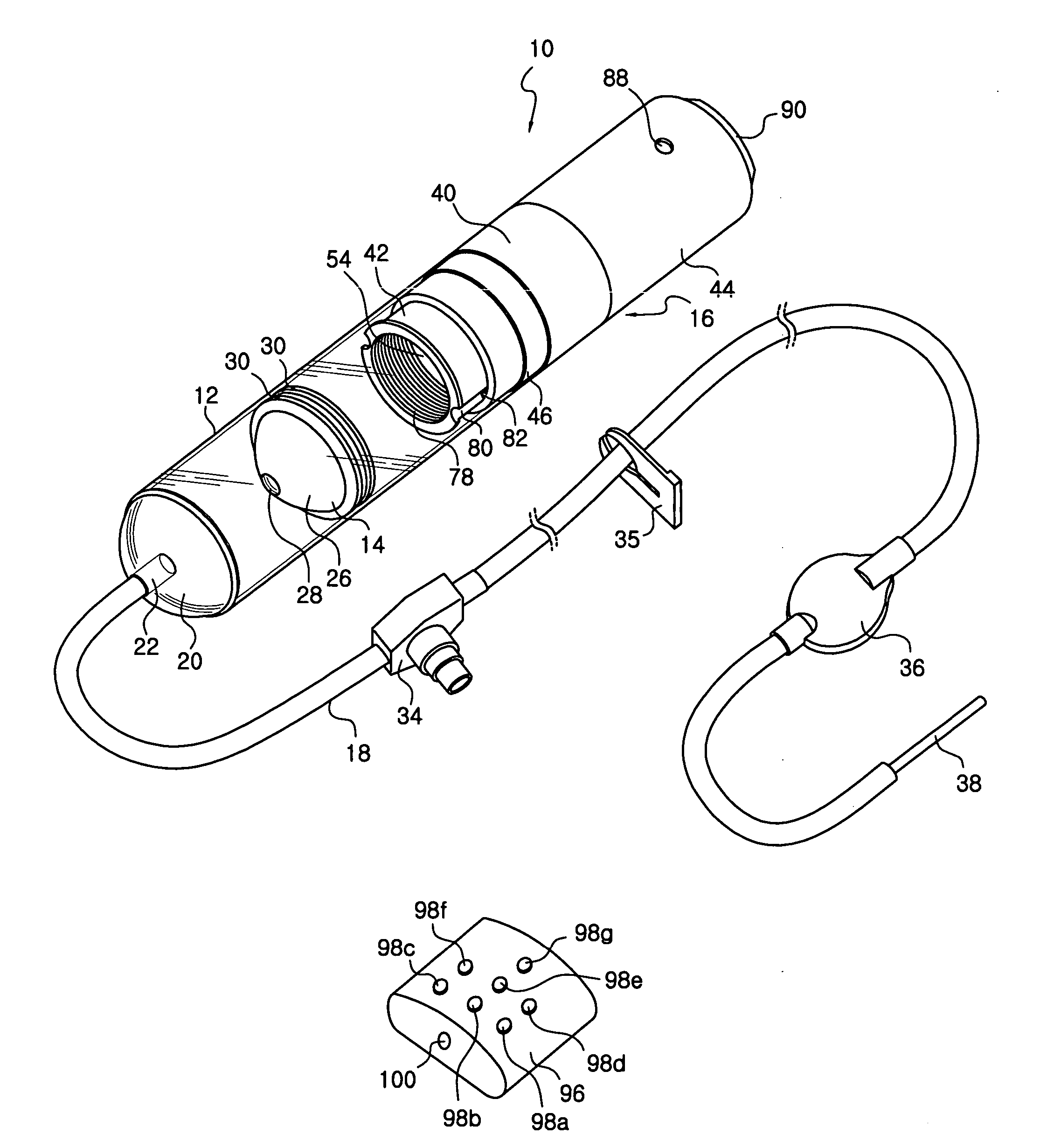
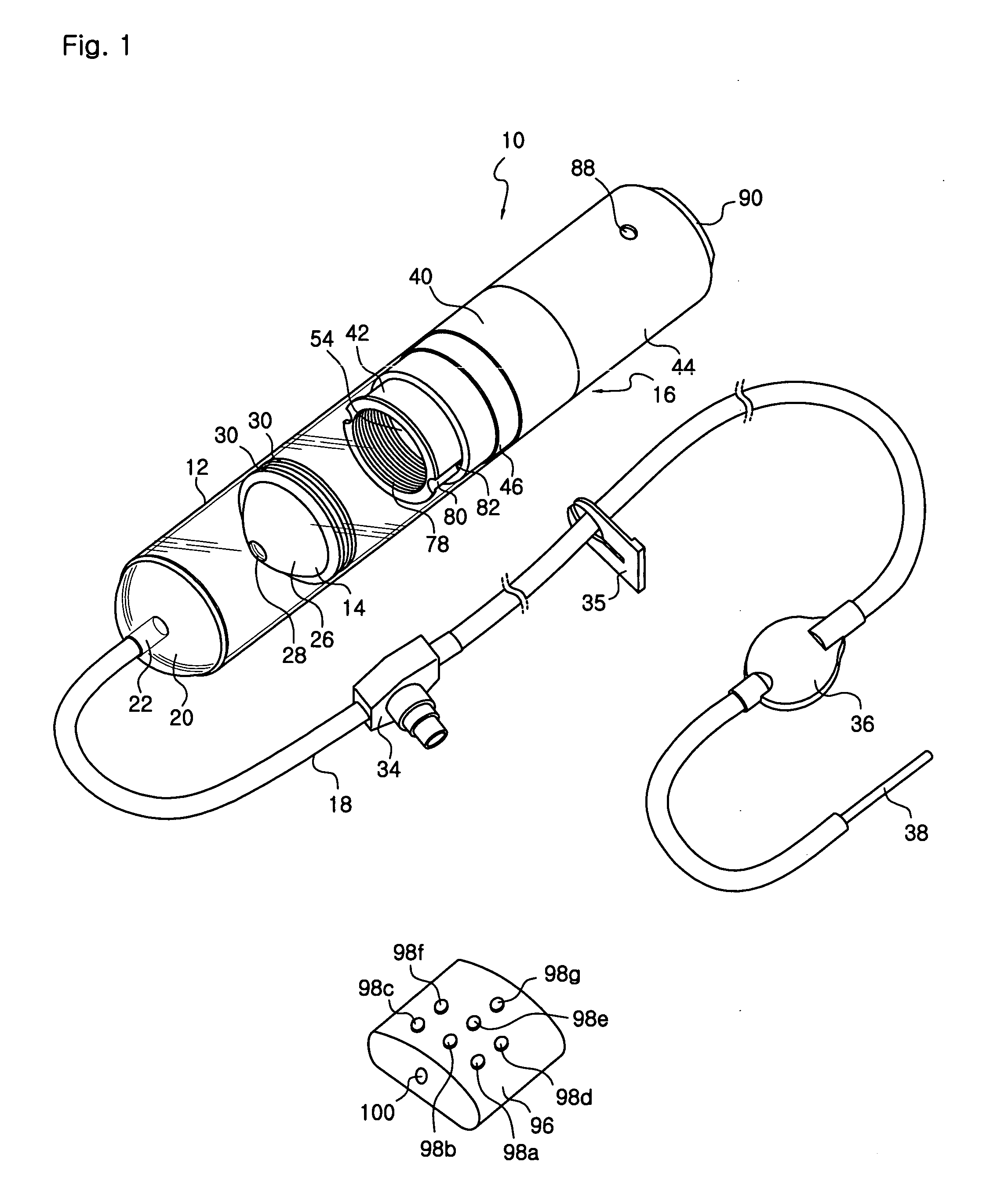
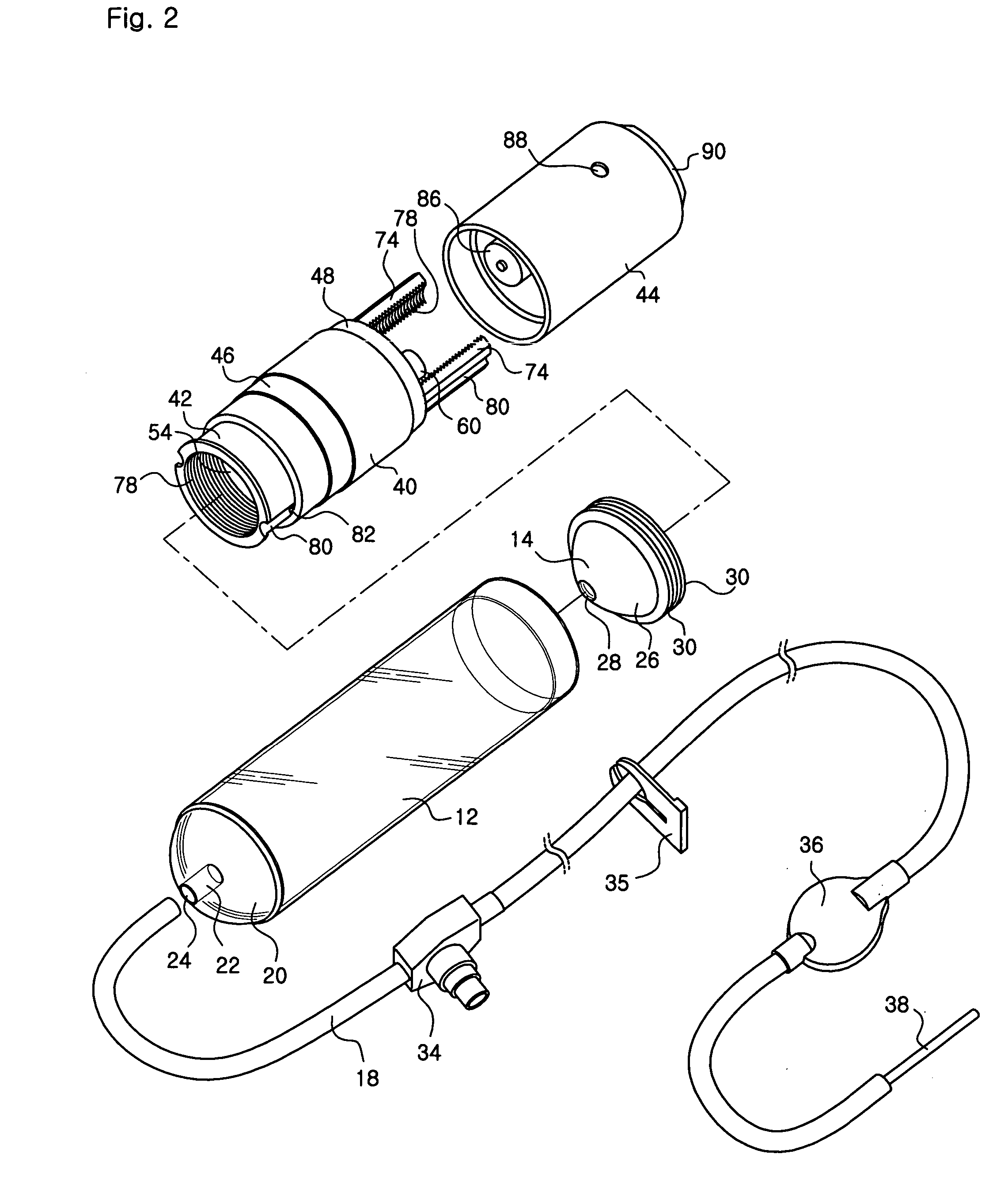
[0039] Referring to FIGS. 1 to 4, a medicine injection apparatus 10 comprises a cylinder 12, a piston 14 and a piston pushing apparatus 16. The piston 14 is fitted into the cylinder 12. A tube 18 is connected to a front end of the cylinder 12. The piston pushing apparatus 16 is intended to move the piston 14 toward a head portion 20 of the cylinder 12 generally at a constant speed.

[0040] The cylinder 12 is hollow and cylindrical, and is generally made of transparent plastic resin material. Although it is not shown, a scale is printed onto an external surface of the cylinder. Referring to FIGS. 1 to 3, the head portion 20 of the cylinder 20 has a generally hemispherical shape and protrudes outwards. (However, the present invention is not limited to the above.) An exhaust projection 22, protruding into the cylinder, is formed at a center of the head portion 2...


PUM


Abstract

A liquid supply apparatus (10) is provided. The liquid supply apparatus (10) has a cylinder (12), a piston (14) and a piston pushing apparatus. The cylinder (12) is provided with a head portion (20) with outlet (24). The cylinder (12) has a rear end opened. The piston (14) is inserted into the cylinder (12). The piston moves along the longitudinal direction of the cylinder (12) so as to inject liquid contained in the cylinder (12). The piston pushing apparatus (16) pushes the piston (14). The piston pushing apparatus (16) has a moving member contacting the rear portion of the piston (14), a electric motor and a movement transferring mechanism. The movement transferring mechanism converts the rotation of the motor into the linear movement of the moving member.

Description

RELATED APPLICATIONS [0001] This application is a continuation of application Ser. No. 10 / 350,165, filed Jan. 21, 2003, which is a continuation application under 35 U.S.C. § 365 (c) of PCT International Application No. PCT / KR00 / 01530 designating the United States, filed Dec. 23, 2000. The PCT Application was published in English as WO 02 / 11791 A1 on Feb. 14, 2002, and claims for the benefit of the earlier filing dates of Korean Patent Application Nos. 2000 / 42128 filed Jul. 22, 2000, and 2000 / 63790 filed Oct. 28, 2000. The contents of the Korean Patent Application Nos. 2000 / 42128 and 2000 / 63790, International Application No. PCT / KR00 / 01530 including the publication WO 02 / 11791 A1, and the prior US application are incorporated herein by reference in its entirety.BACKGROUND OF THE INVENTION [0002] 1. Field of the Invention [0003] The present invention relates to a liquid supply apparatus, more particularly to a portable liquid supply apparatus that is constructed so that liquid medicin...

Claims


Application Information

Patent Timeline
Patent Type & Authority Applications(United States)
IPC IPC(8): A61M5/00A61M5/14A61M5/142A61M5/145A61M5/168A61M5/20A61M39/00A61M39/02
CPCA61M5/1452A61M5/14526A61M5/16831A61M39/20A61M2205/7536A61M2005/14506A61M2039/205A61M2205/3592A61M2205/50A61M2005/14204A61M2005/31516A61M5/00
Inventor KIM, YONG-NYUN
Owner E WHA FRESENIUS KABI
Why Eureka
Try Eureka