Method and apparatus for guiding side edges of continuously running web

a technology of side edges and continuous running webs, applied in the direction of web handling, manufacturing tools, transportation and packaging, etc., can solve the problems of difficulty in shifting side edges in directions other than outward direction, and difficulty in continuously making articles each having a high dimensional accuracy

Inactive Publication Date: 2005-03-17
NOMURA HIRONORI +2
View PDF10 Cites 41 Cited by
  • Summary
  • Abstract
  • Description
  • Claims
  • Application Information

AI Technical Summary

Benefits of technology

[0007] It is an object of the present invention to provide a method and an apparatus facilitating the side edges of the web continuously running in the machine direction to be quickly guided to desired positions in the cross direction when these side edges are detected to be out of coincidence with the desired positions in the cross direction.

Problems solved by technology

However, it is difficult to shift the side edges in the directions other than the outward direction, for example, inward in the cross direction.
In consequence, it is difficult to continuously make articles each having a high dimensional accuracy by utilizing the side edges of the web.

Method used


Image

  • Method and apparatus for guiding side edges of continuously running web
  • Method and apparatus for guiding side edges of continuously running web
  • Method and apparatus for guiding side edges of continuously running web

Examples


Embodiment Construction

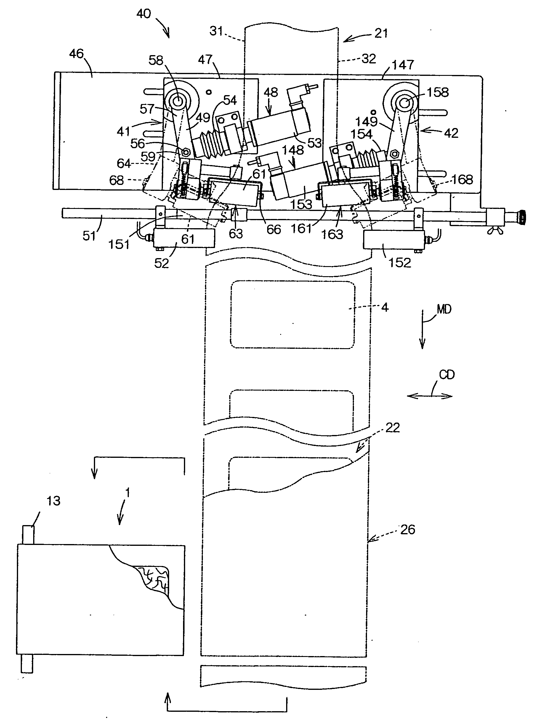
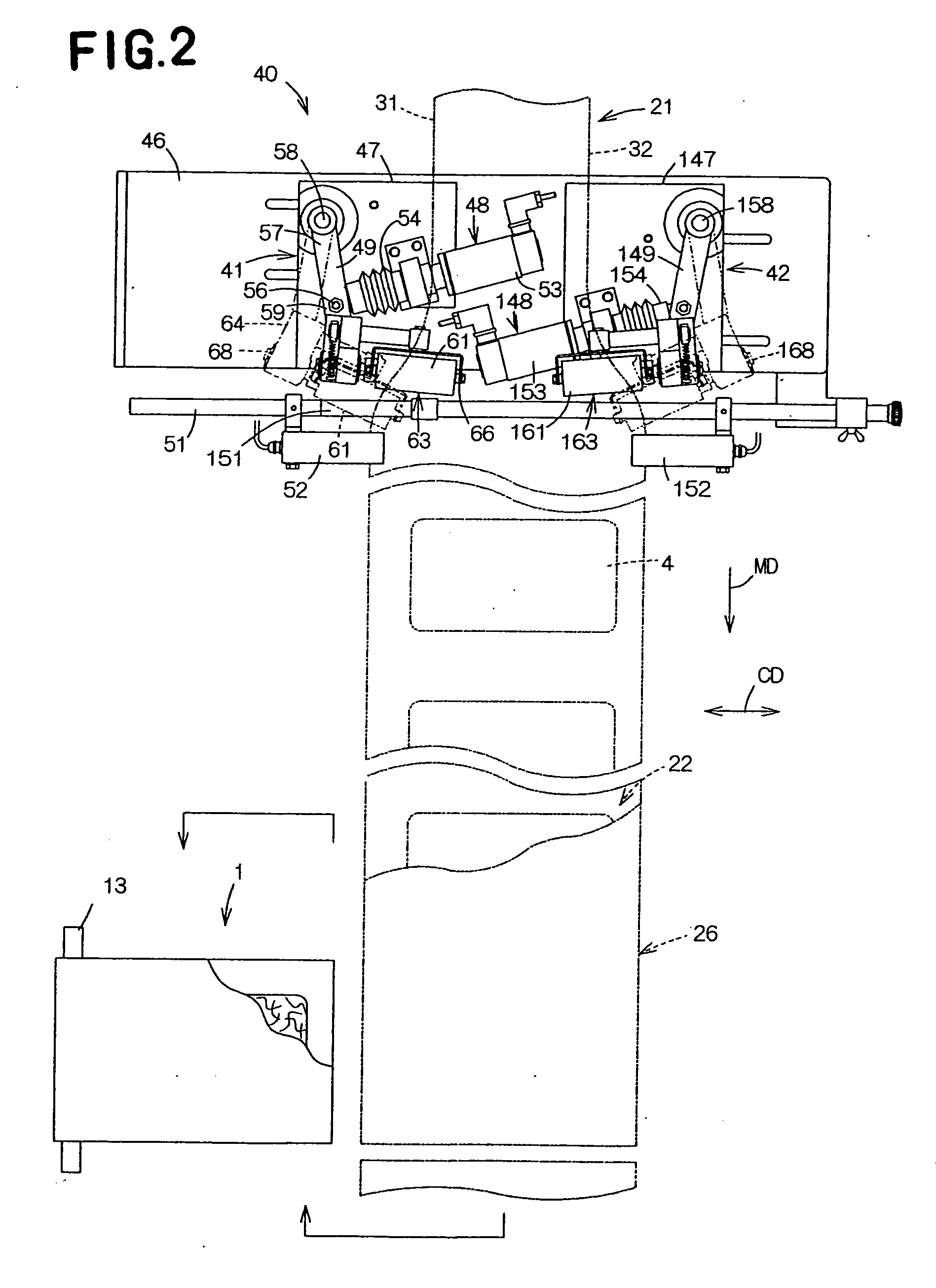
[0032] Details of a method and an apparatus according to the present invention will be more fully understood from the description given hereunder with reference to the accompanying drawings.

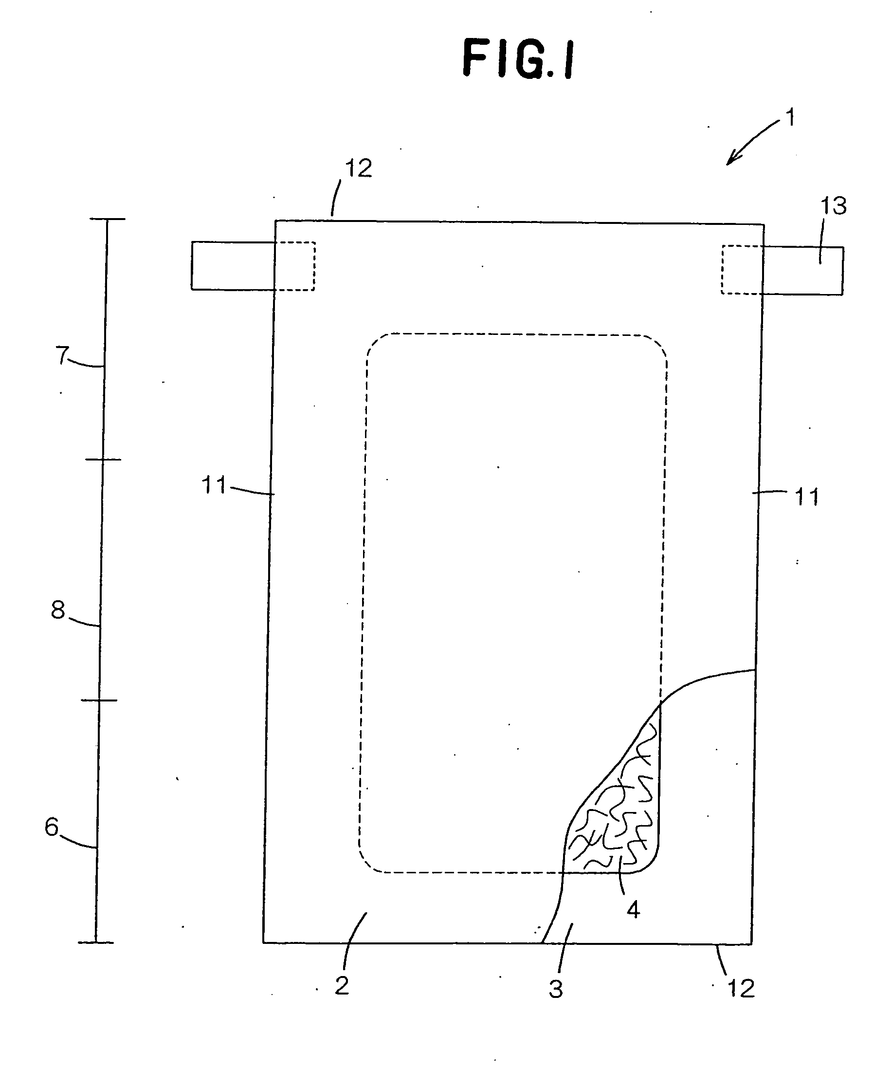
[0033] A disposable diaper 1 shown by FIG. 1 in a plan view as partially broken away is a product obtained by a method and an apparatus according to the present invention. This diaper 1 comprises a liquid-pervious topsheet 2, a liquid-impervious backsheet 3 and a liquid-absorbent core 4 interposed between these sheets 2, 3. The diaper 1 has a in- and outward direction (longitudinal direction as viewed in FIG. 1) and a waist-surrounding direction (transverse direction as viewed in FIG. 1). The diaper 1 is peripherally contoured by a pair of side edges 11 extending parallel to each other in the in- and outward direction and a pair of ends extending parallel to each other in the waist-surrounding direction. As viewed in the in- and and outward direction, the diaper 1 is composed of a front waist re...


PUM


Abstract

The present invention is to provide a method and an apparatus facilitating side edges of a web continuously running in a machine direction to be quickly corrected when these side edges are detected to be out of coincidence with a positions in a cross direction orthogonal to the machine direction. Roll means rotating about a shaft extending in a direction defined between a machine direction and a cross direction are put in contact with side edge of a web continuously running in the machine direction. The shaft is mounted on an arm adapted to rotate back-and-forth so that the shaft can swing in- and outward in the cross direction. Downstream of the roll means, the side edge is position-detected and the arm is made swing by a desired angle determined on the basis of a difference between the actual position and a desired position.

Description

BACKGROUND OF THE INVENTION [0001] The present invention relates to a method and an apparatus allowing, in the course of continuously feeding a flexible web of nonwoven fabric, plastic film, paper or the like in a machine direction, side-edges of such a web to be guided to desired positions in a cross direction orthogonal to the machine direction. [0002] It is well known in prior art references 1, 2, 3 listed below, in the course of continuously feeding a flexible web of nonwoven fabric, plastic film, paper or the like in a machine direction, to put guide roll means rotating about respective shafts each obliquely extending at a desired angle with respect to the machine direction in contact with the vicinities of side edges of such a web and thereby to move the side edges so that the web may be broadened. It is also well known that the web can be unwrinkled by guiding the side edges of the web. Prior art reference discloses a method for guiding the side edges of the web continuously ...

Claims


Application Information

Patent Timeline
Patent Type & Authority Applications(United States)
IPC IPC(8): A61F13/15B65H23/025B65H23/038
CPCA61F13/15764B65H23/038B65H23/0251A61F13/15772
Inventor NOMURA, HIRONORISHIMAKAWA, TAIJIYAMAMOTO, HIROKI
Owner NOMURA HIRONORI
Why Eureka
Try Eureka