Bundle target coupling sensor

A sensor-target coupling technology, applied in the field of photoelectric sensors, can solve problems such as the inability to guarantee the accuracy and reliability of target shooting, the difficulty of designing and assembling the monitoring system, deformation and scattering, etc., to shorten the laser guidance time, realize visualization, and improve adaptability Effect

Inactive Publication Date: 2010-02-17
HARBIN INST OF TECH
View PDF6 Cites 11 Cited by
  • Summary
  • Abstract
  • Description
  • Claims
  • Application Information

AI Technical Summary

Problems solved by technology

[0003] In order to solve the problems that the existing monitoring system is difficult to design, process and assemble, the cost is high, deformation and scattering are easy to occur, and the accuracy and reliability of shooting cannot be guaranteed for special targets, the present invention proposes a beam-target coupling sensor

Method used


Image

  • Bundle target coupling sensor
  • Bundle target coupling sensor
  • Bundle target coupling sensor

Examples


specific Embodiment approach 1

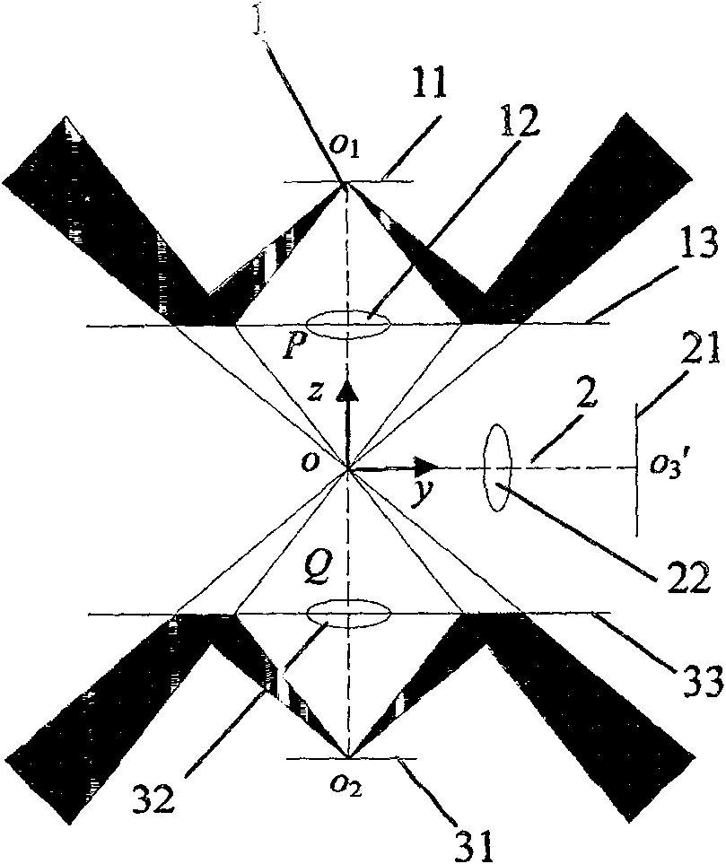
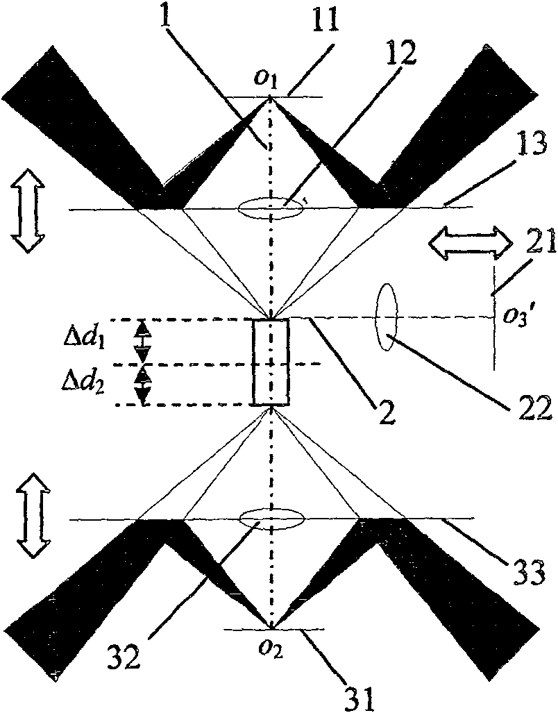
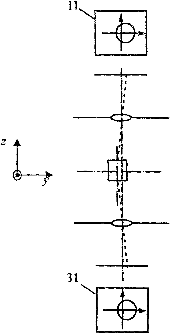
[0018] Specific implementation mode one: combine figure 1 , figure 2 with Figure 6 to Figure 10 Describe this embodiment, the beam-target coupling sensor in this embodiment is composed of an upper monitoring unit, a middle monitoring unit, a lower monitoring unit, and a focusing mechanism;

[0019] The upper monitoring unit is composed of an upper CCD11, an upper microscope objective lens 12, an upper laser reflector 13 and an upper annular LED light source 14;

[0020] There is a circular hole in the middle of the upper laser reflector 13, and the upper microscopic objective lens 12 is fixed on the central position of the circular hole, and the optical axis of the upper microscopic objective lens 12 is perpendicular to the reflection surface of the upper laser reflective mirror 13 , the top of the upper microscopic objective lens 12 is provided with an upper road CCD11, and the upper annular LED light source 14 is installed on the bottom of the upper laser reflector 13. ...

specific Embodiment approach 2

[0028] Specific implementation mode two: combination Figure 6 to Figure 10 Describe this embodiment, the difference between this embodiment and the specific embodiment is that the upper support frame 41, the lower support frame 42 and the middle monitoring unit support 44 are added; the upper support frame 41, the lower support frame 42 and the middle monitoring unit support 44 are respectively Used to fix the upper monitoring unit, lower monitoring unit and middle monitoring unit. Other compositions and connection methods are the same as those in Embodiment 1.

specific Embodiment approach 3

[0029] Specific implementation mode three: combination Figure 6 to Figure 10 Describe this embodiment, the difference between this embodiment and specific embodiment 2 is that the focus adjustment mechanism is composed of an upper focus adjustment mechanism, a lower focus adjustment mechanism, a middle focus adjustment mechanism 53 and a focus adjustment mechanism support frame 43; the upper focus adjustment mechanism is composed of an upload Moving mechanism 511, upper focusing vacuum motor 512 and upper rotating gear 513; The lower rotating gear 523 is composed of: the lower focusing mechanism is used to vertically adjust the position of the lower support frame 42, and the upper focusing vacuum motor 512 and the lower focusing vacuum motor 522 are installed in the focusing mechanism support frame 43; the lower focusing vacuum motor The drive shaft of 522 is connected to the lower rotating gear 523 of the focusing mechanism support frame 43 bottom, and the lower rotating gea...


PUM


Abstract

The invention relates to a beam-target coupling sensor belonging to the field of photoelectric sensors, which overcomes the problems with conventional monitoring systems including high difficulties indesign, manufacture, and assembling, high cost, high liability to undesired phenomena such as distortion and scattering, as well as low ensurance for targeting accuracy and reliability concerning special targets. The sensor includes three monitoring elements including an upper one, an intermediate one, and a lower one, each including a CCD, a micro object lens, a laser reflector, and an annular LED light source for monitoring the spatial position and posture of a target. The annular LED is used for illuminating the target. An incident laser beam on a target point is reflected onto the image surface of the CCD via the laser reflector. A vacuum motor and a ball screw transmission pair are used to realize focusing of the upper and lower micro monitoring systems, and an electric micro displacement platform is used to realize focusing of the intermediate micro monitoring system. In addition to accurate and fast guiding, the invention realizes zero impact of the target on light beam guidingbecause of indirect cast of laser light thereon, thus achieves improved adaptability to different targets.

Description

technical field [0001] The invention relates to the field of photoelectric sensors. Background technique [0002] The laser inertial confinement fusion experiment is one of the most cutting-edge research topics in the world at present. The experiment realizes the fusion reaction by bombarding the deuterium-tritium target with multiple high-energy lasers, thereby realizing controllable fusion. In the laser inertial confinement fusion experiment, it is necessary to guide multiple laser beams to the specified position on the experimental target. In the past, the laser guidance method is to directly hit the laser on the target and monitor the position of the light spot on the target through the monitor. Since the wavelength of the target laser is usually ultraviolet light, and the light detected by the monitoring system is in the visible light band, the distance between the target and the light spot To monitor the chromatic aberration, the solution to the chromatic aberration p...

Claims


Application Information

Patent Timeline
Patent Type & Authority Patents(China)
IPC IPC(8): G01B11/00G21B1/11G02B7/04G02B5/08
CPCY02E30/14Y02E30/10
Inventor 刘国栋刘炳国庄志涛陈凤东胡涛浦昭邦
Owner HARBIN INST OF TECH
Why Eureka
Try Eureka