Linear actuator

a linear actuator and actuator technology, applied in the direction of positive displacement liquid engine, magnet body, piston pump, etc., can solve the problems of difficult to improve performance, poor reliability, feeder line cut, etc., and achieve the effect of improving reliability and improving performan

Inactive Publication Date: 2005-03-17
SHINKO ELECTRIC CO LTD
View PDF4 Cites 59 Cited by
  • Summary
  • Abstract
  • Description
  • Claims
  • Application Information

AI Technical Summary

Benefits of technology

[0007] Accordingly, an object of the present invention is to provide a linear actuator in which reliability is improved, and performance is also easily improved.

Problems solved by technology

In the linear actuator of movable coil type, a problem is encountered in that reliability is inferior because the movable element includes a coil, electrical current must be supplied to the movable element, and feeder lines may be cut due to the movement of the movable element.
In addition, in the linear actuator of movable magnet type, a problem is encountered in that it is difficult to improve performance because the weight of the permanent magnet is increased when high magnetic flux density is to be obtained, and the weight of the movable element is increased.

Method used


Image

  • Linear actuator
  • Linear actuator
  • Linear actuator

Examples


first embodiment

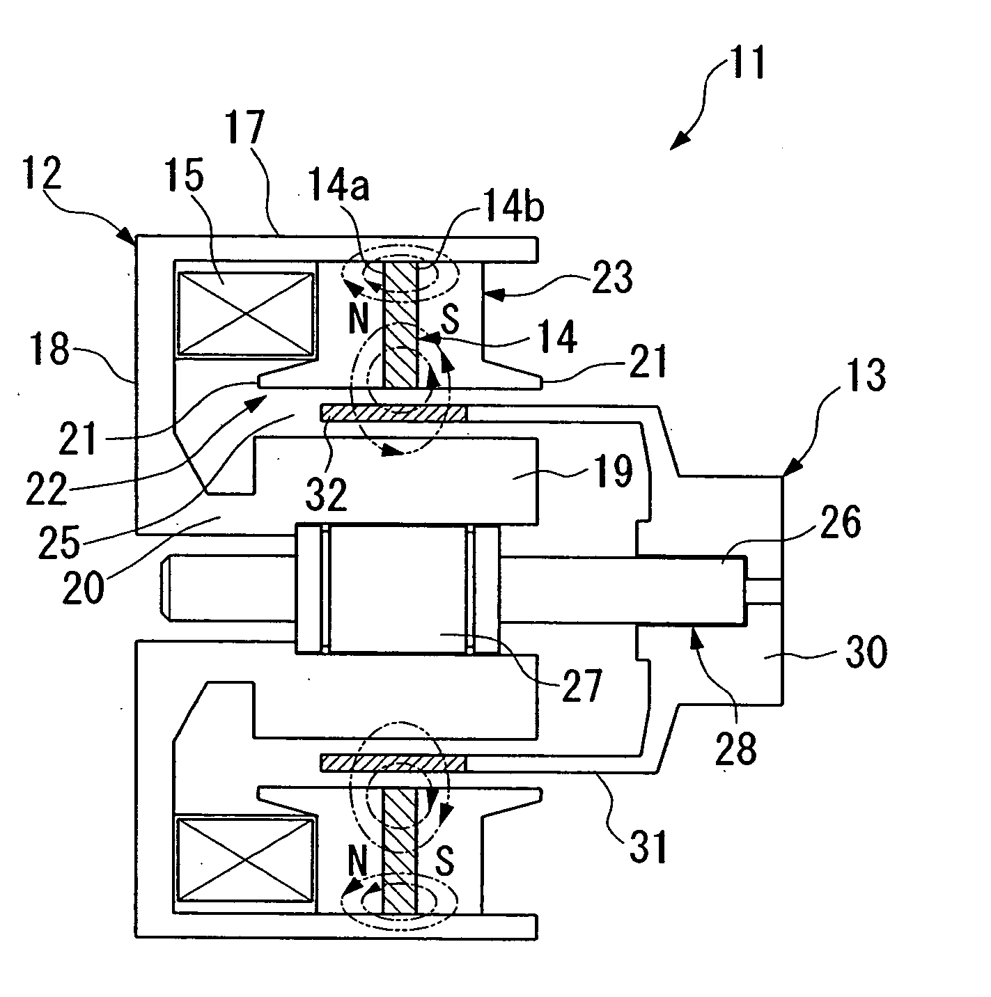
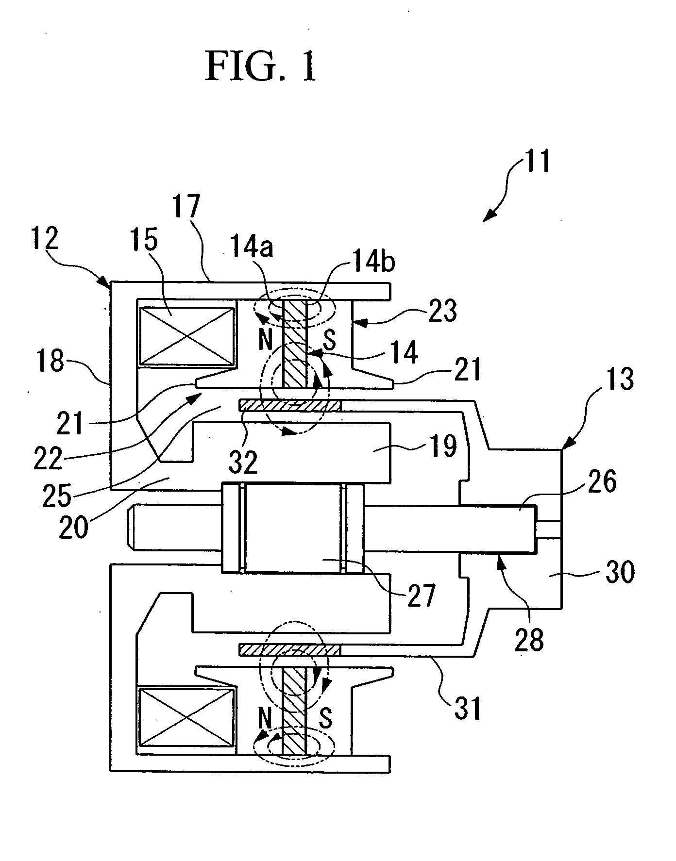
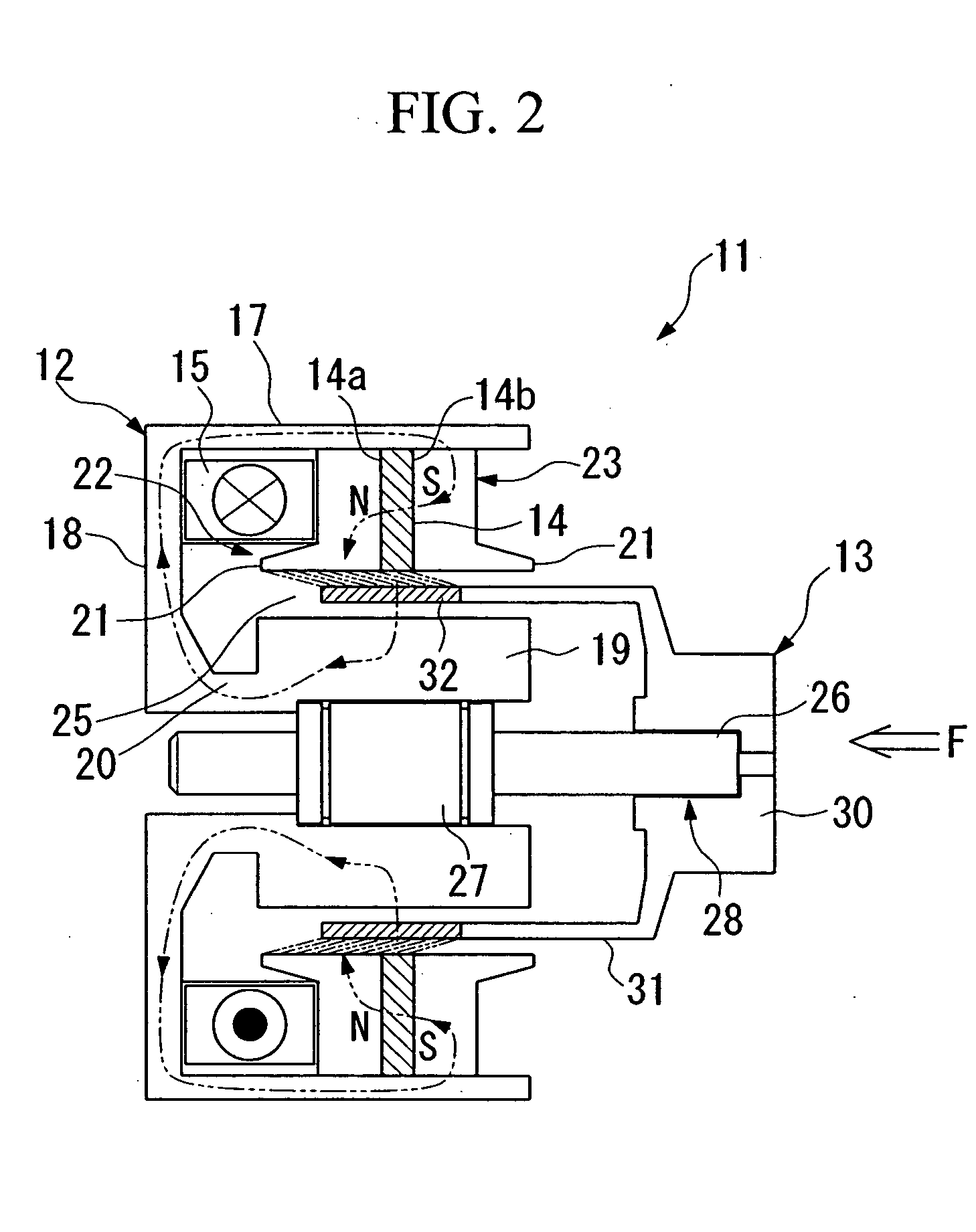
[0140] the linear actuator according to the present invention will be explained below with reference to FIGS. 1 to 4.

[0141] A linear actuator 11 according to the first embodiment includes a yoke (stator) 12, a movable element 13 which is reciprocatable with respect to the yoke 12, a permanent magnet 14 fixed to the yoke 12, and a coil 15 fixed to the yoke 12.

[0142] The yoke 12 includes an outer cylindrical portion 17 having a cylindrical shape, a bottom plate 18 having a thin ring shape and disposed at one side in the axial direction with respect to the outer cylindrical portion 17, a ring-shaped connection portion 20 extending in the axial direction from an inner portion of the bottom plate 18 toward the same side as the outer cylindrical portion 17 extends, a cylindrical inner magnetic pole (magnetic pole element) 19 provided on the connection portion 20 so as to be coaxial with the outer cylindrical portion 17.

[0143] The yoke 12 including the outer cylindrical portion 17, the b...


PUM

PropertyMeasurementUnit
cylindrical shapeaaaaaaaaaa
magnetic polesaaaaaaaaaa
magneticaaaaaaaaaa

Abstract

An object of the present invention is to provide a linear actuator in which reliability is improved, and performance is also easily improved. The present invention provides a linear actuator including a stator, a movable element having an iron member, and being reciprocatable with respect to the stator, a permanent magnet fixed to the stator so as to be opposed to the iron member, and a coil fixed to the stator. Because both the coil and the permanent magnet are fixed to the stator, electrical current does not have to be supplied to the movable element, and the feeder lines connected to the coil will not be broken due to the movement of the movable element. In addition, the weight of the movable element will not be increased even when the weigh of the permanent magnet is increased in order to obtain high magnetic flux density for improvement in performance. Moreover, because the movable element does not include a magnet, a magnetizing operation does not have to be applied to the movable element. The permanent magnets may be a pair in which the directions the magnetic poles thereof differ from each other, and two pairs of permanent magnets may be provided. The number of magnetic fluxes that run through the magnetic pole elements and the iron member can be increased by providing a magnetic reluctance section around the permanent magnets.

Description

TECHNICAL FIELD [0001] The present invention relates to a linear actuator, and in particular, relates to improvements in reliability and performance of a linear actuator. BACKGROUND ART [0002] Because linear actuators can be driven with little loss by employing a spring therein for utilizing a resonance phenomenon, they have been used as compressor motors. Because the compressors employing such linear motors exhibit excellent performance such as high efficiency, it is expected that such compressors will be used for refrigerators, freezers, and air conditioners. [0003] As a linear actuator, a voice coil motor is known. In the voice coil motor, electrical current is made to flow through a coil within a magnetic field formed by permanent magnets so that a force to drive the voice coil motor is applied to the coil. Such a voice coil motor is referred to as a movable coil type in which a movable element including a coil is moved. [0004] Another type of linear actuator is also known, in w...

Claims


Application Information

Patent Timeline
Patent Type & Authority Applications(United States)
IPC IPC(8): H01F7/08H01F7/122H01F7/16H02K21/44H02K33/00H02K33/02H02K33/16H02K41/03
CPCH01F7/081H01F7/122H01F7/1615H02K7/085H02K33/00H02K33/16H02K41/033H02K21/44H02K41/02H02K41/03H02K41/025
Inventor NAKAGAWA, HIROSHIKATO, KAZUMICHIMIKI, TOSHIOMAEDA, MINORUFUKUNAGA, TAKASHIFURUTANI, KOZOSUGIMOTO, TOSHIYA
Owner SHINKO ELECTRIC CO LTD
Why Eureka
Try Eureka