Light emission control circuit uniformly and non-uniformly controlling a plurality of light-emitting elements

Inactive Publication Date: 2005-03-17
ROHM CO LTD
View PDF1 Cites 44 Cited by
  • Summary
  • Abstract
  • Description
  • Claims
  • Application Information

AI Technical Summary

Benefits of technology

[0009] The present invention is done in view of the above-described circumstances and an object thereof is to provide

Problems solved by technology

It is difficult to control the tone of color an

Method used


Image

  • Light emission control circuit uniformly and non-uniformly controlling a plurality of light-emitting elements
  • Light emission control circuit uniformly and non-uniformly controlling a plurality of light-emitting elements
  • Light emission control circuit uniformly and non-uniformly controlling a plurality of light-emitting elements

Examples


Embodiment Construction

[0025] The invention will now be described based on the following embodiments which do not intend to limit the scope of the present invention but exemplify the invention. All of the features and the combinations thereof described in the embodiments are not necessarily essential to the invention.

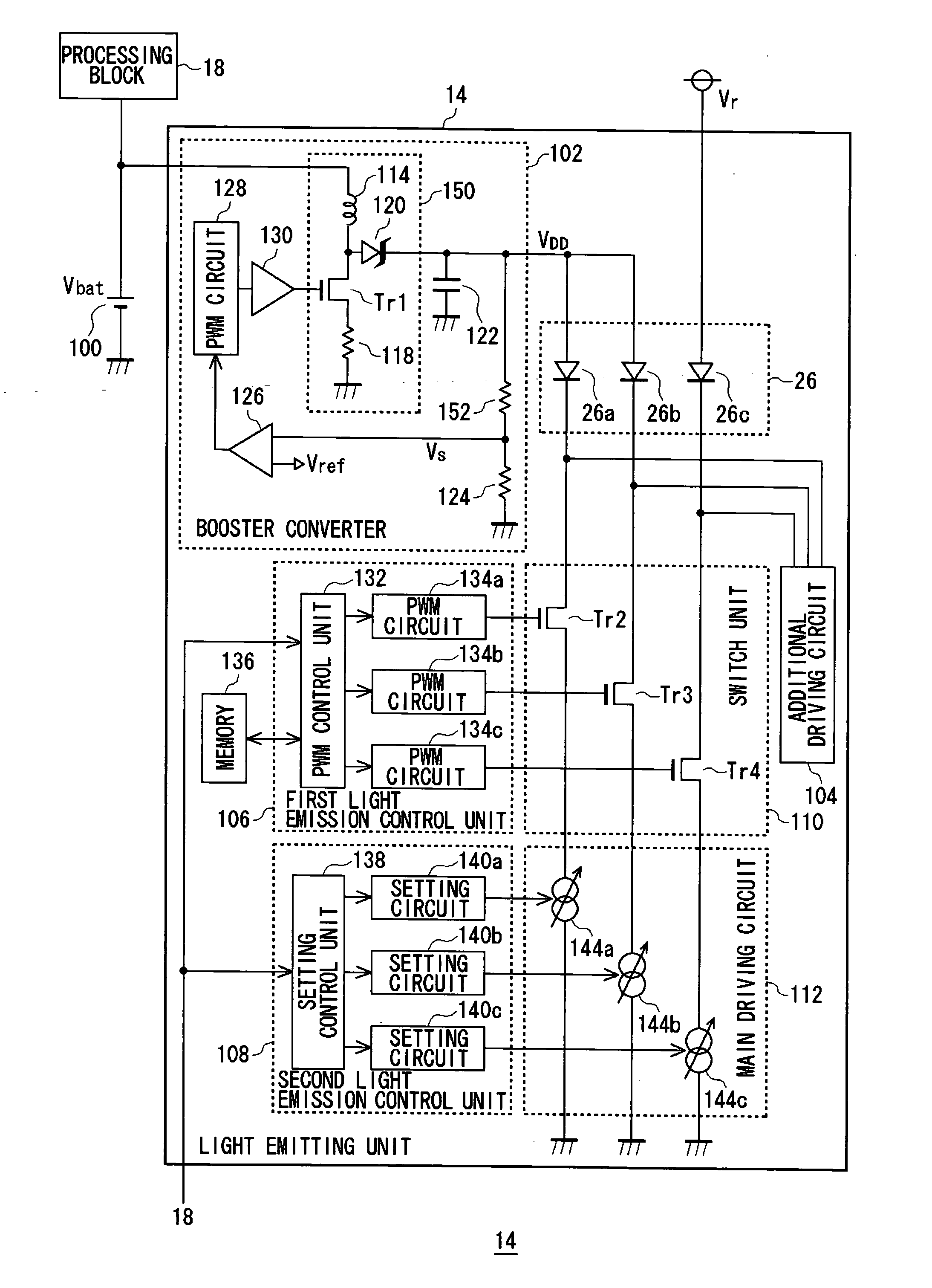
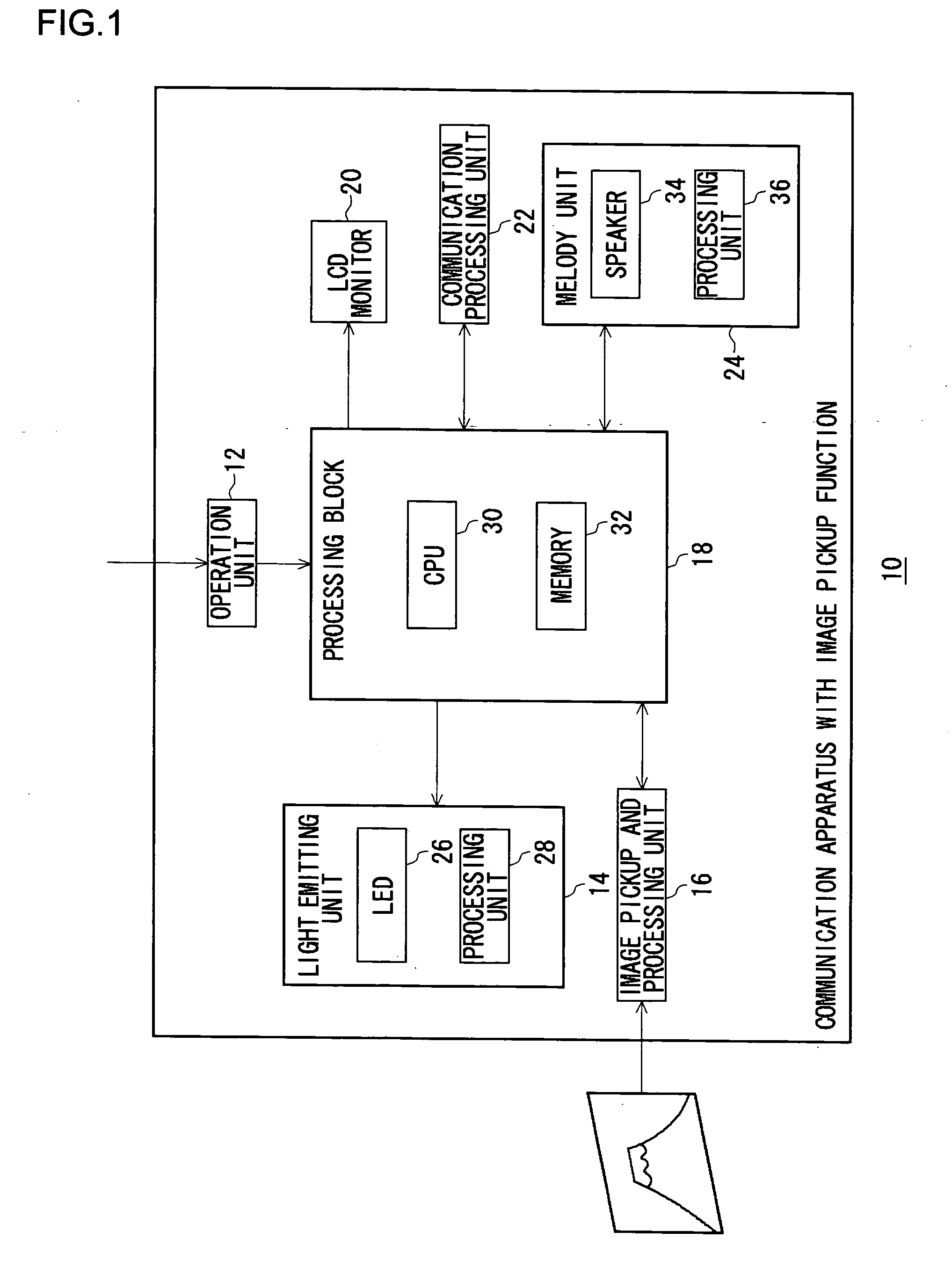
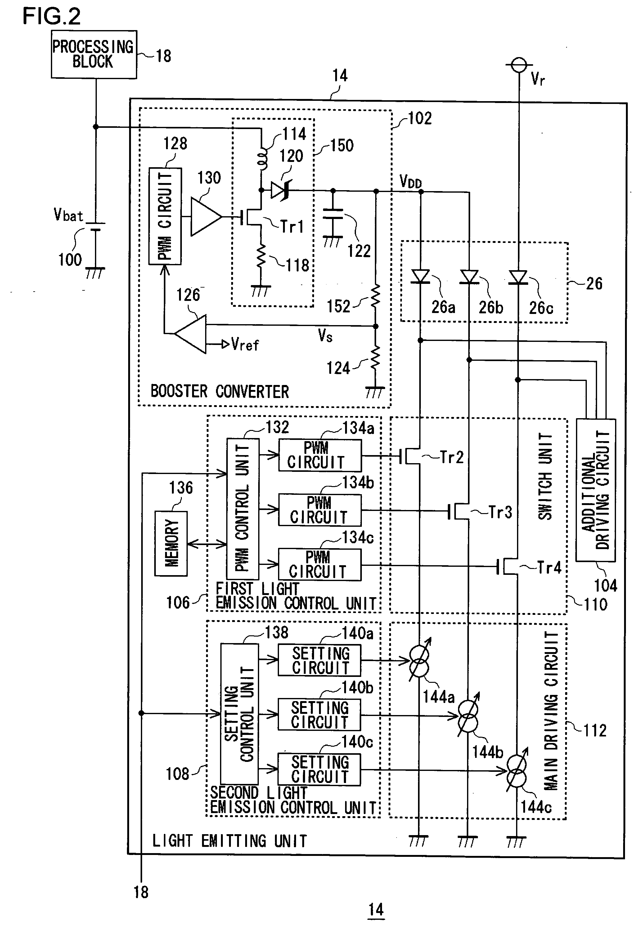
[0026] Before describing the present invention in detail, a summary of will be given. An embodiment of the present invention relates to a control apparatus for controlling the light emission of a plurality of LEDs provided in a communication apparatus such as a portable telephone. A plurality of LEDs include green LEDs, blue LEDs and red LEDs. For example, selected ones of the LEDs blink in a predetermined pattern to provide illumination responsive to incoming call sound of the communication apparatus. In one mode of light emission, a single LED is lighted. In others, a plurality of LEDs are lighted simultaneously so that the color of light emitted by the entirety of the LEDs is different fr...


PUM


Abstract

A booster converter outputs a boosted voltage. A plurality of LEDs emit light of respective colors. The transistors establish or shut connection between the LEDs and a main driving circuit. A variable current circuit feeds a current to drive the LEDs. A PWM control unit effects control to cause the LEDs to emit light with respective tones of color. A PWM circuit executes PWM modulation in accordance with an instruction from the PWM control unit. A setting control unit 138 controls the magnitude of the driving current fed by the variable current circuit in accordance with an instruction from a second light emission control unit. In an image pickup mode, an additional driving circuit feeds a driving current to the LEDs so that the LEDs operate as an electronic flash.

Description

BACKGROUND OF THE INVENTION [0001] 1. Field of the Invention [0002] The present invention relates to a light emission control technique and, more particularly, to a light emission control circuit controlling light emission of a plurality of light-emitting elements. [0003] 2. Description of the Related Art [0004] Battery-driven portable equipment such as a portable telephone and a personal data assistant (PDA) use light-emitting diodes (LED) for a variety of purposes. For example, LEDs are used to provide backlight for a liquid crystal display (LCD) or an electronic flash light for a charge-coupled device (CCD) camera. LEDs emitting different colors are operated to blink for illumination. Patent Document No. 1 describes the use of blue, green and red LEDs and mixing of colors emitted by these diodes to produce colors other than blue, green and red for illumination. Light emission of an LED is controlled according to the pulse width modulation (PWM) method. Three LEDs are connected to...

Claims


Application Information

Patent Timeline
IPC IPC(8): G09G3/30G09G3/32G09G5/00H01L33/00H04M1/00H04M1/02H04M1/22H05B37/02H05B44/00
CPCH05B33/0815Y02B20/346H05B33/0863H05B33/0827H05B45/20H05B45/46Y02B20/30H05B45/38G09G3/32
Inventor YAMAMOTO, ISAOMIYANAGA, KOICHI
Owner ROHM CO LTD
Why Eureka
Try Eureka