
Camera image shake correcting device

a technology for correcting devices and camera images, which is applied in the direction of color television details, television system details, television systems, etc., can solve the problems of image shake correction means, camera shake may appear as significant shake, and the camera shake is likely to occur when, so as to improve the correction response to image shake, prevent image quality degradation, and reduce cost

Inactive Publication Date: 2005-03-17
HASEGAWA TAKAMI
View PDF2 Cites 50 Cited by
  • Summary
  • Abstract
  • Description
  • Claims
  • Application Information

AI Technical Summary

Benefits of technology

[0008] The present invention was made to solve the above-described problems with the background art. Accordingly, it is an object of the present invention to provide a camera image shake correcting device that employs image shake correcting means using an optical system to prevent image quality degradation and that uses a lightweight and compact mirror to allow improvement of correction response to image shake as well as miniaturization and to achieve a cost reduction. That is, the present invention provides the following:

Problems solved by technology

Therefore, slight shake of the camera system may appear as significant shake in the photographed image.
Consequently, camera shake is likely to occur when taking pictures.
The image shake correcting means suffers, however, from the disadvantage that the image quality is unavoidably degraded because all the effective pixel area of the solid-state image sensor cannot be used to read the image signal.
Therefore, there are limits to the improvement of correction response to camera shake, and the reduction in size of the system is also limited.

Method used


Image

  • Camera image shake correcting device
  • Camera image shake correcting device
  • Camera image shake correcting device

Examples


Embodiment Construction

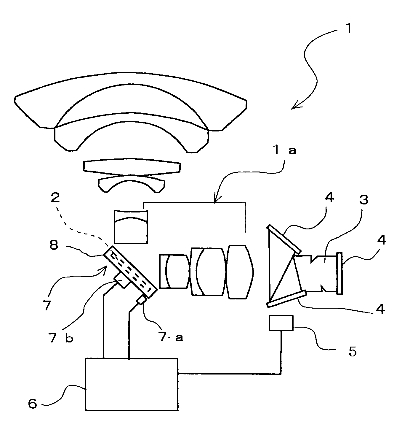
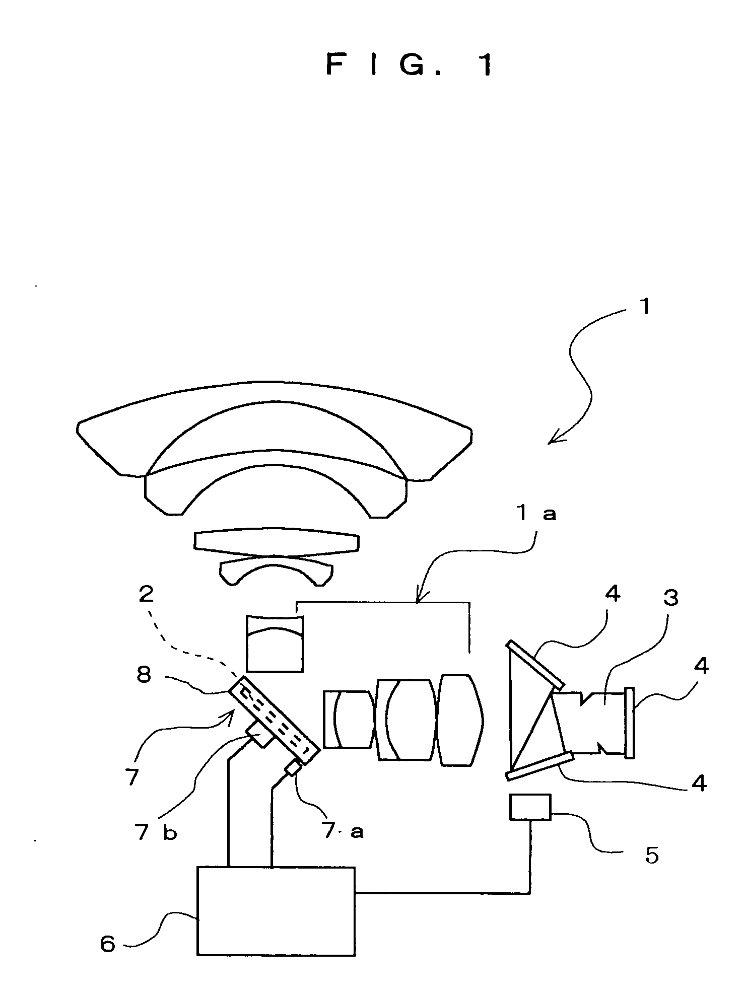
[0037] An embodiment of the present invention will be described below on the basis of an example in which the present invention is applied to a 3-CCD video camera as shown in FIG. 1.

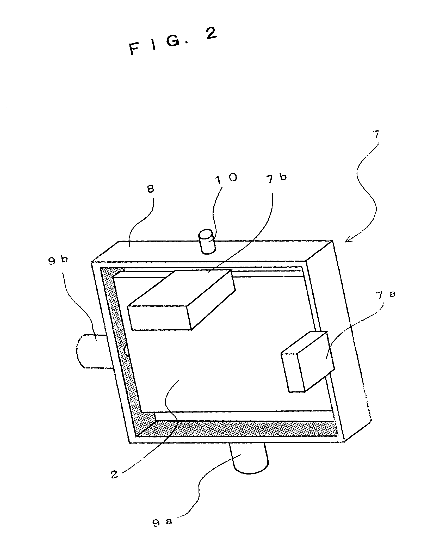
[0038] The camera image shake correcting device according to the present invention comprises, as seen in FIG. 1, a mirror 2 disposed in an intermediate portion of an optical path along which light entering an image pickup optical system of the camera travels to reach solid-state image sensors 4. The mirror 2 is pivotable in both an X axis direction and a Y axis direction. A mirror driving means 7 pivots the mirror 2 in the X axis and Y axis directions so that displacement of a subject image on each solid-state image sensor 4 caused by shake of the camera is corrected by a change in the reflection angle of the mirror 2. A displacement sensor unit 5 detects the direction and amplitude of shake of the camera or the direction and magnitude of displacement of the subject image on the solid-state image sensor...


PUM


Abstract

A camera image shake correcting device is provided which employs an image shake correcting system using an optical system to prevent image quality degradation and which uses a mirror (2) to allow improvement of correction response to image shake as well as miniaturization and to achieve a cost reduction. The camera image shake correcting device is characterized by having a mirror (2) disposed in an intermediate portion of an optical path connecting together an image-formation plane of an image pickup optical system of a camera and an imaging lens; mirror driving means (7) for driving the mirror (2) so that the angle of the mirror (2) is changed in correspondence to displacement of an image on the image-formation plane caused by shake of the camera to cancel the displacement of the image on the image-formation plane; and control means (6) for controlling the mirror driving means (7) by detecting the amount of shake of the camera or the amount of displacement of the image on the image-formation plane.

Description

TECHNICAL FIELD OF THE INVENTION [0001] The present invention relates to a camera image shake correcting device wherein image shake caused by camera shake when taking pictures is reduced by using an optical system, particularly a mirror. BACKGROUND ART [0002] Recently, camera systems such as still cameras and video cameras have been equipped with various functions contributing to automation of photographing, e.g. automatic exposure control and automatic focusing control, and such camera systems have been put to practical use. One of the automating functions is camera image shake correcting means for reducing image shake due to camera shake, that is, hand shake, when taking pictures. The camera image shake correcting means is adopted as an essential function in most digital cameras and video cameras, particularly those that use a solid-state image sensor as an image pickup device and record image signals in a semiconductor memory or the like, for the following reasons: [0003] 1) Came...

Claims


Application Information

Patent Timeline
IPC IPC(8): H04N5/232
CPCH04N5/23248H04N5/23287H04N5/23258H04N5/23254H04N23/68H04N23/6811H04N23/6812H04N23/687
Inventor HASEGAWA, TAKAMI
Owner HASEGAWA TAKAMI
Learn More