Eureka AIR delivers breakthrough ideas for toughest innovation challenges, trusted by R&D personnel around the world.

Image scanning apparatus

Inactive Publication Date: 2005-03-17
SEIKO EPSON CORP
View PDF10 Cites 8 Cited by
  • Summary
  • Abstract
  • Description
  • Claims
  • Application Information

AI Technical Summary

Benefits of technology

[0018] The present invention also enables the use of a single scanner IC chip preferably a CIS chip comprising an IC control circuit to control the operation of and signal processing of a plurality of image scanners disposed in a single image scanning apparatus representing a single system. Multiple image scanning sensors can thus be used in a single system without the need for a different signal processing circuit, control circuit, and other peripheral elements for each image scanner. This permits the construction of a compact control circuit board.

Problems solved by technology

Flatbed scanners are necessarily large because space sufficient for the scan head to traverse the entire surface of the scanned medium must be provided for inside the scanner.
The need to apply an appropriate pressure commensurate with the thickness of the medium complicates the construction of the scanning apparatus.
This increases the cost and the size of the control circuit board.

Method used


Image

  • Image scanning apparatus
  • Image scanning apparatus
  • Image scanning apparatus

Examples


Embodiment Construction

[0025] A preferred embodiment of an image scanning apparatus according to the present invention is hereafter described in detail below with reference to the accompanying figures.

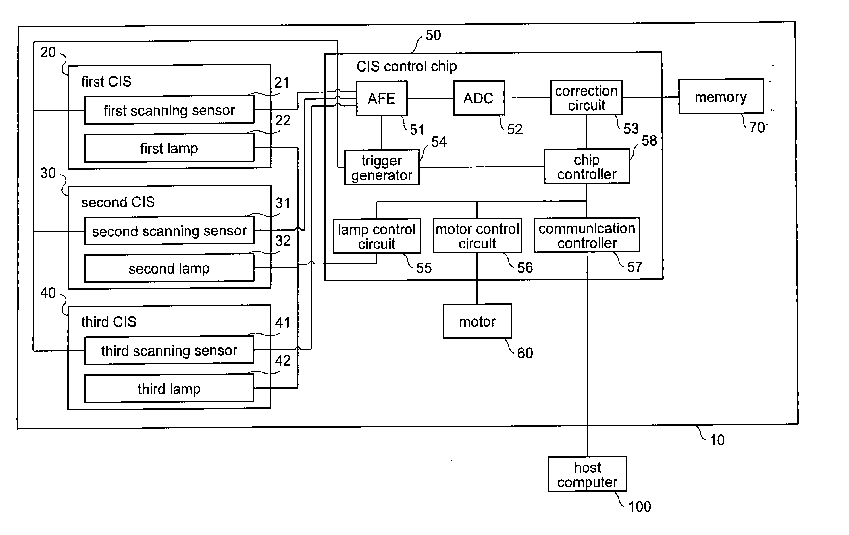
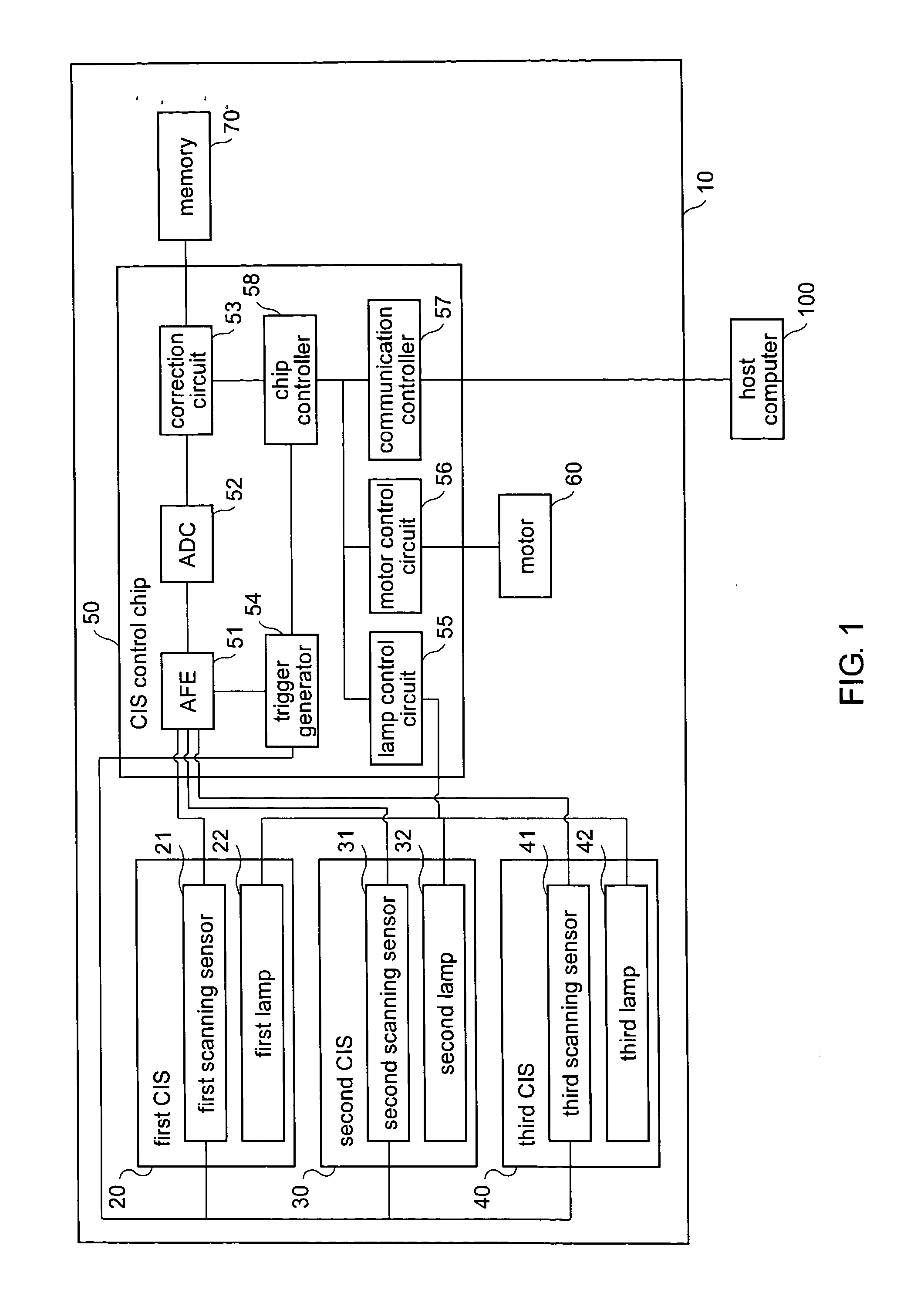
[0026] One embodiment of the image scanning apparatus 10 of this invention is shown in FIG. 1 comprising a first CIS 20, a second CIS 30, a third CIS 40, a CIS control chip 50, a motor 60, and a memory 70 which operate under the control of a host computer 100 preferably located external of the image scanning apparatus 10. The CIS control chip 50 controls the first CIS 20, the second CIS 30, and the third CIS 40 i.e., the first CIS 20, the second CIS 30, and the third CIS 40 are controlled from the same control system using only one control chip.

[0027] The three contact image scanners 20, 30, and 40 are hereafter described in detail.

[0028] The first CIS 20 has a first lamp 22 for illuminating a first medium (hereafter “first scanned medium”), and a first scanning sensor 21. The first scanning sensor 21 sca...


PUM


Abstract

An image scanning apparatus comprising a plurality of image scanning sensors 21, 31, 41, and a CIS control chip 50 for controlling these image scanning sensors 21, 31, 41. The CIS control chip 50 has a trigger generator 54 for controlling operation of the image scanning sensors 21, 31, 41, a lamp control circuit 55, and a motor control circuit 56. The CIS control chip 50 also has an AFE 51 having a plurality of input terminals 51a to 51c for receiving the analog image signals from the first scanning sensor 21, second scanning sensor 31, and third scanning sensor 41, respectively and a gain / offset control circuit for adjusting the gain and offset of each line of analog data supplied from the image scanning sensors 21, 31, 41.

Description

BACKGROUND OF THE INVENTION [0001] 1. Field of Technology [0002] The present invention relates to an image scanning apparatus having a plurality of image scanning sensors. [0003] 2. Description of Related Art [0004] Image scanners are commonly used to scan image data printed on the surface of paper, cards, and other source media. Such image scanners emit light from an LED or other light source disposed in the scan head in the direction of the medium to be scanned while the medium being scanned is held against the scan head. An image scanning sensor disposed in the scan head then detects the light reflected back from the scanned medium to take an image of the scanned medium. [0005] There are two basic types of image scanning sensors, flatbed and sheetfed. With a flatbed scanner, the medium to be scanned remains stationary while the scan head travels relative to the medium for taking an image of the scanned medium. With sheetfed scanners, the scan head remains stationary while the med...

Claims


Application Information

Patent Timeline
IPC IPC(8): H01J3/14H04N1/028G06T1/00H04N1/04H04N1/407H04N1/48
CPCH04N1/0464H04N1/486H04N1/407
Inventor KASUGA, HIROAKIIMAIZUMI, ATSUYUKI
Owner SEIKO EPSON CORP
Why Eureka
Eureka Blog
Learn More