Image processing apparatus

a processing apparatus and image technology, applied in the field of image processing apparatus, can solve problems such as deterioration of image quality, diagonal deterioration of resolution in appearance, and error in determining correlation direction, and achieve the effect of reducing adverse effects upon interpolation results

Inactive Publication Date: 2005-03-17
CANON KK
View PDF6 Cites 36 Cited by
  • Summary
  • Abstract
  • Description
  • Claims
  • Application Information

AI Technical Summary

Benefits of technology

[0023] The present invention is also capable of reducing adverse effects upon the interpolation result caused by an error in determination of the correlation direction when pixels contain frequency com

Problems solved by technology

Accordingly, when the simultaneous interpolation process is generally performed by cascading vertical and horizontal low-pass filters, interpolation optimum for such a rhombic frequency domain cannot be achieved, thus resulting in a deterioration of image quality.
However, the related art is disadvantageous because a satisfactory interpolation process based on the correlation cannot be performed for pixels having correlation in directions other than the vertical and horizontal directions, and resoluti

Method used


Image

  • Image processing apparatus
  • Image processing apparatus
  • Image processing apparatus

Examples


first embodiment

[0058] (First Embodiment)

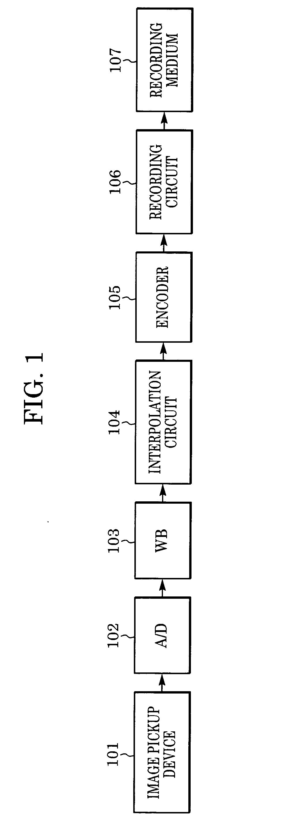
[0059]FIG. 1 is a block diagram of a video camera in accordance with an embodiment of the present invention.

[0060] Referring to FIG. 1, an image pickup device 101 has color filters of a primary-color Bayer array shown in FIG. 24, and outputs RGB image signals corresponding to the color filters in respective pixels. The image signals output from the image pickup device 101 are converted into digital signals by an A / D converter 102 and are subjected to a white balance adjusting process in a white balance circuit (WB) 103. Resulting signals are then output to an interpolation circuit 104. The interpolation circuit 104 is designed in accordance with the present invention, and outputs a result obtained by performing a simultaneous interpolation process of G signals from RGB color values as described later. The image signals output from the interpolation circuit 104 are subjected to a known coding process in an encoder 105 and then recorded on a recording medium ...

second embodiment

[0117] (Second Embodiment)

[0118] A second embodiment will now be described.

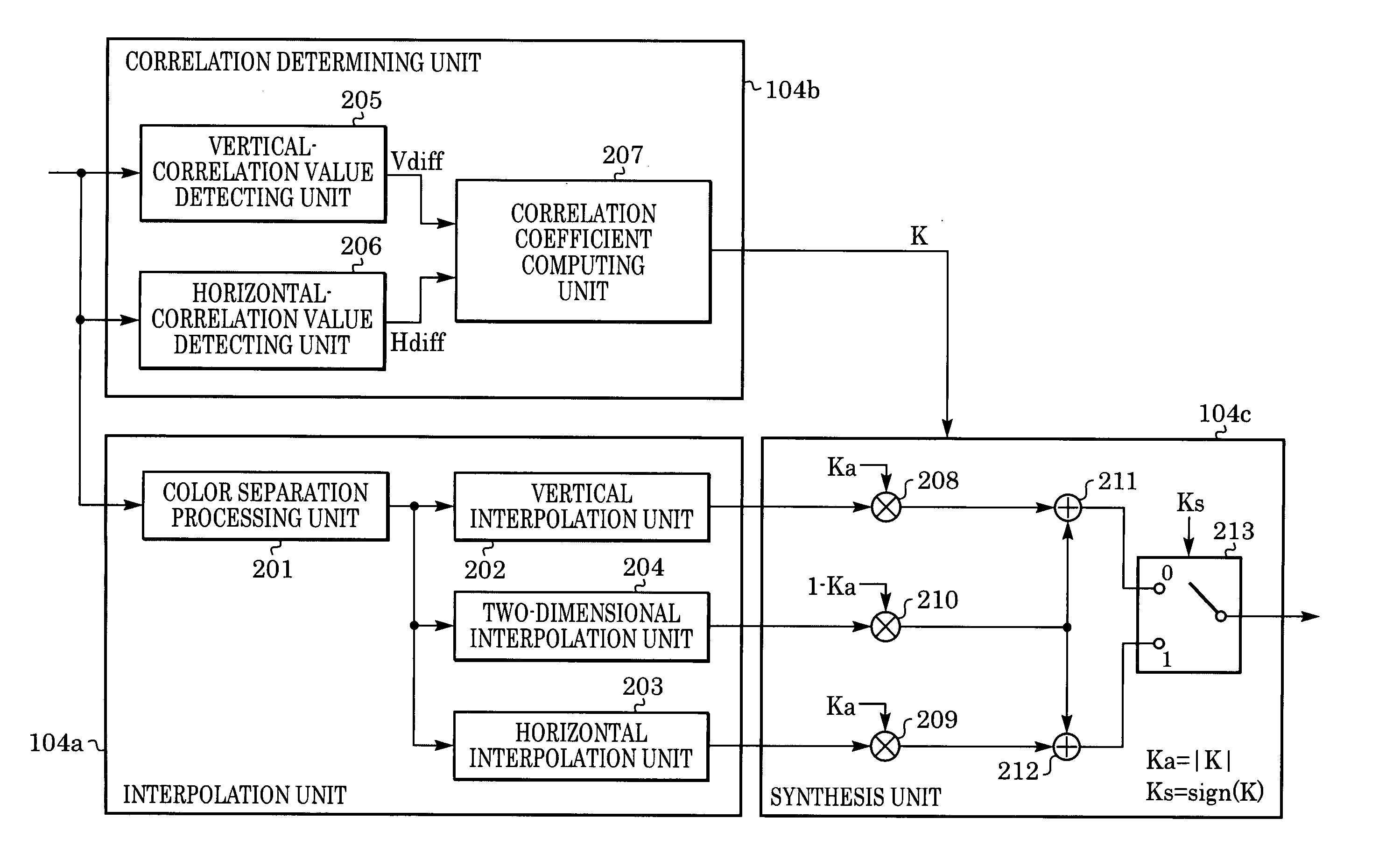
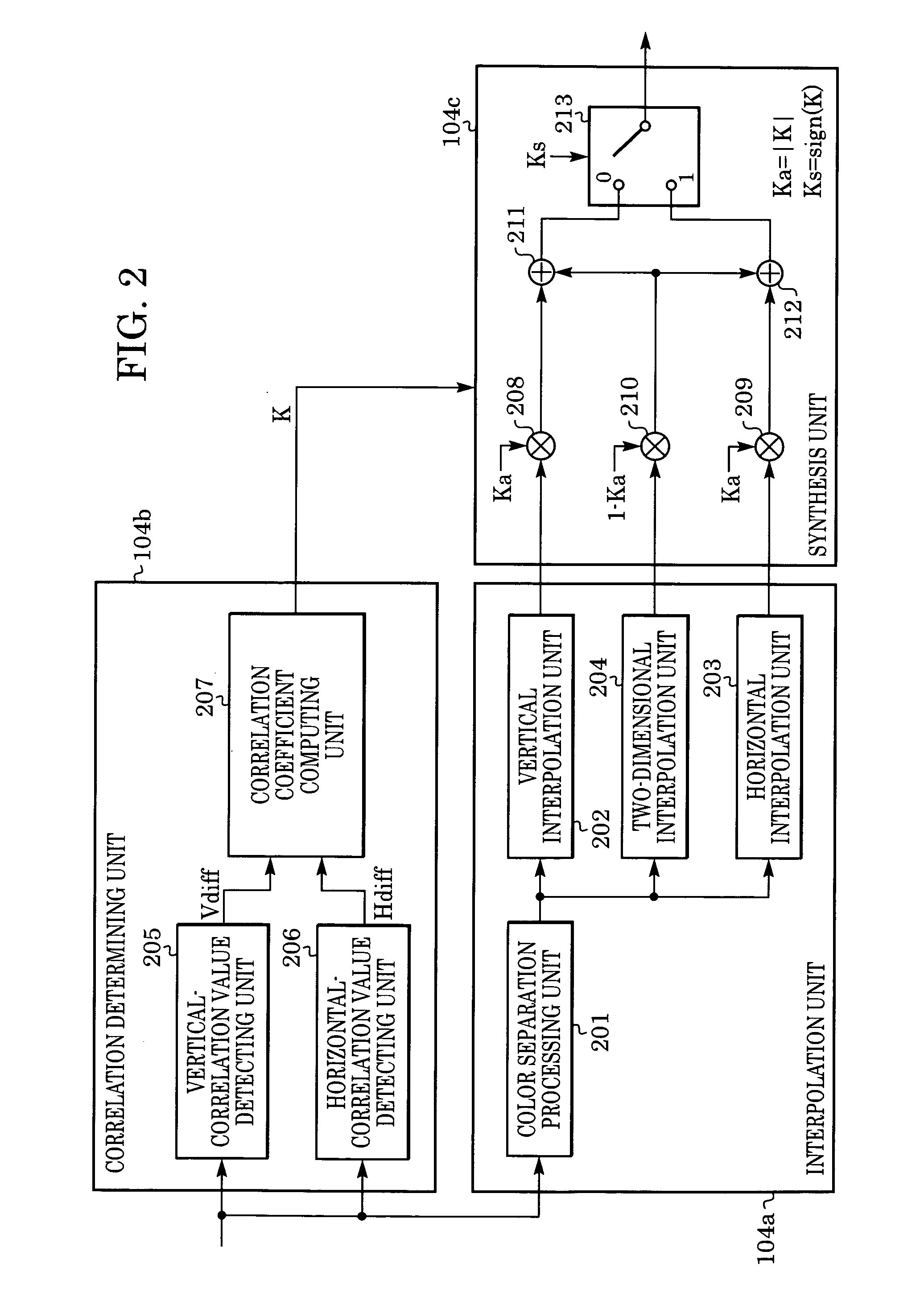
[0119] An interpolation circuit of the second embodiment has a similar basic configuration to that of the first embodiment shown in FIG. 2. The second embodiment differs from the first embodiment in the correlation coefficient computing unit 207 of the correlation determining unit 104b. Therefore, the following description is made of the correlation coefficient computing unit 207, and the other components are not described here.

[0120] The processing executed in this embodiment by the correlation determining unit 104b to output the correlation coefficient K from the correlation coefficient computing unit 207 based the output signals of the vertical correlation value detecting unit 205 and the horizontal correlation value detecting unit 206, i.e., Vdiff and Hdiff, will be described below with reference to the flowchart of FIG. 13.

[0121] Referring to FIG. 13, respective values of Hdiff and Vdiff are first com...

third embodiment

[0136] (Third Embodiment)

[0137]FIG. 15 is a block diagram of an interpolation circuit 104 according to a third embodiment of the present invention. In FIG. 15, components similar to those in FIG. 2 are denoted by the same numerals.

[0138] Referring to FIG. 15, input image signals are processed in an interpolation unit 104a and a correlation determining unit 104b in parallel. Then, respective output signals from the two units 104a, 104b are input to a synthesis unit 104c that outputs a final result of the simultaneous interpolation process of G signals.

[0139] The interpolation unit 104a is first described. In the interpolation unit 104a, G-signal pixels to be interpolated are extracted by a color separation processing unit 201 and then output to four interpolation units 202, 203, 214 and 215 connected in parallel. The color separation processing unit 201 is similar to that of the first embodiment, and a description thereof is omitted here.

[0140] Processing in each interpolation uni...


PUM


Abstract

An image processing system has an input unit for inputting an image signal obtained with offset sampling per pixel, a correlation detecting unit for, based on the input image signal, producing a coefficient depending on an arbitrary direction in which correlation between a plurality of pixels near a target pixel to be interpolated is high, and an interpolation circuit for producing an interpolation image signal in accordance with the coefficient produced by the correlation detecting unit, and interpolating the image signal input from the input unit by using the interpolation image signal.

Description

CROSS REFERENCED TO RELATED APPLICATIONS [0001] This application claims priority from Japanese Patent Application No. 2003-321421 and 2003-321422 filed Sep. 12, 2003, which is hereby incorporated by reference herein. BACKGROUND OF THE INVENTION [0002] 1. Field of the Invention [0003] The present invention relates to an image processing apparatus, and more particularly to an interpolation process for sampled image signals. [0004] 2. Description of the Related Art [0005] Digital still cameras and video cameras have become quite popular among consumers. These cameras typically have image pick up devices that employ a color filter system known as the primary-color Bayer array. [0006] As shown in FIG. 24, the Bayer array is patterned such that each pixel has an R, G, or B color value. To obtain other color values for each pixel, an interpolation process using nearby pixels having the desired color value is required. For example, a G value can be obtained for a B pixel by interpolating G ...

Claims


Application Information

Patent Timeline
IPC IPC(8): G06K9/40G06T3/40H04N5/228H04N9/04
CPCG06T3/4007H04N2209/046H04N9/045G06T3/4015H04N23/843H04N25/134
Inventor TAJIMA, KAORI
Owner CANON KK
Why Eureka
Try Eureka