Method and apparatus for hydrogen detection and dilution

a technology of hydrogen detection and dilution, applied in the field of fuel cells, can solve the problems of migration and cross-contamination, and achieve the effect of reducing the number of contaminated samples

Active Publication Date: 2005-03-17
GM GLOBAL TECH OPERATIONS LLC
View PDF11 Cites 33 Cited by
  • Summary
  • Abstract
  • Description
  • Claims
  • Application Information

AI Technical Summary

Problems solved by technology

Such migration and cross-co

Method used


Image

  • Method and apparatus for hydrogen detection and dilution
  • Method and apparatus for hydrogen detection and dilution
  • Method and apparatus for hydrogen detection and dilution

Examples


Embodiment Construction

[0020] The following description of the preferred embodiments is merely exemplary in nature and is in no way intended to limit the invention, its application, or uses.

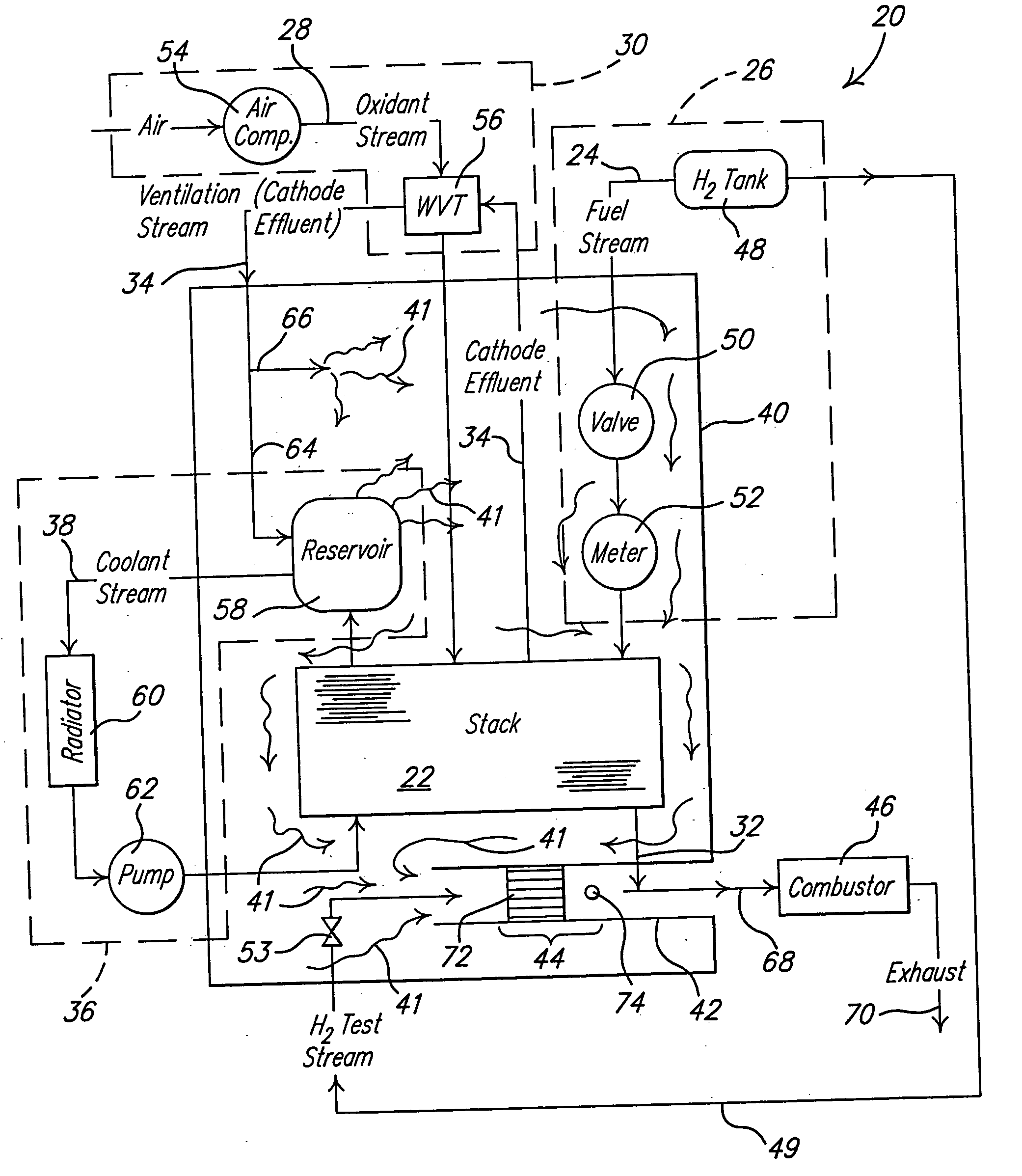
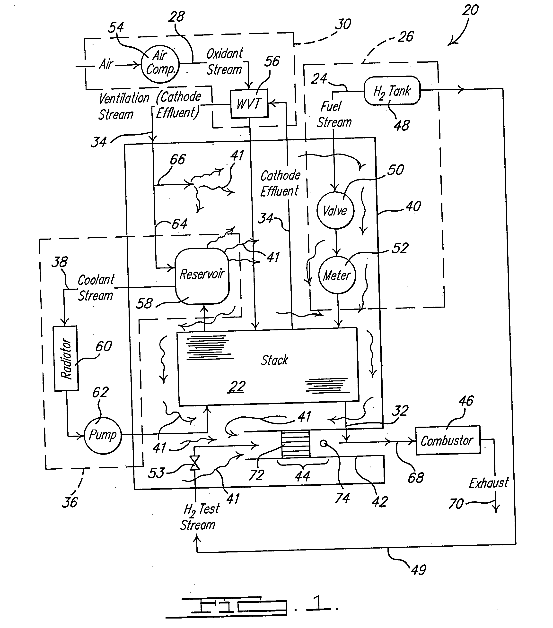
[0021] A first preferred embodiment of a fuel cell system according to the principles of the present invention is shown in FIG. 1 and generally indicated as 20. Fuel cell system 20 includes a fuel cell stack 22 that is comprised of a plurality of individual fuel cells assembled together to form the stack. Fuel cell stack 22 is operable to react a hydrogen-containing fuel stream 24 supplied by a fuel delivery system 26 and an oxygen-containing oxidant stream 28 provided by an oxidant delivery system 30 to generate electrical power. The reaction of the hydrogen-containing fuel stream 24 with the oxygen-containing oxidant stream 28 within fuel cell stack 22 produces a hydrogen-containing anode effluent stream 32 and an oxygen-containing cathode effluent stream 34 in addition to the generation of electrical power. A coola...


PUM


Abstract

The present invention provides for a method and apparatus for hydrogen detection and dilution. The present invention uses an enclosure within which a variety of components of a fuel cell system are located and a ventilation stream to vent the enclosure which is induced by operation of a compressor that also is operable to supply the oxygen to the fuel cell system. The ventilation stream is directed through an outlet in the enclosure that contains a hydrogen sensor that is operable to both detect the presence of hydrogen and to consume hydrogen within the ventilation stream prior to being exhausted from the enclosure. The ventilation stream, alternatively, can be induced by operation of a fan driven by a motor which operates independently of the operation of the oxidant delivery system.

Description

FIELD OF THE INVENTION [0001] The present invention relates generally to fuel cells and, more particularly, to methods and apparatuses to detect hydrogen migration in a fuel cell system. BACKGROUND OF THE INVENTION [0002] H2—O2(air) fuel cells are well known in the art and have been proposed as a power source for many applications both mobile and stationary. There are several types of H2—O2 fuel cells including acid-type, alkaline-type, molten-carbonate-type, and solid-oxide-type. A plurality of individual cells are commonly bundled together to form a fuel cell stack. In these fuel cells hydrogen is the anode reactant (i.e., fuel) and oxygen is the cathode reactant (i.e., oxidant). The oxygen can either be in a pure form (i.e., O2), or air (i.e., O2 mixed with N2). During the conversion of the anode reactant and cathode reactant to electrical energy, the fuel cell, regardless of the type, produces anode and cathode effluents that are exhausted from the fuel cell stack. [0003] The fu...

Claims


Application Information

Patent Timeline
IPC IPC(8): H01M8/04
CPCH01M8/04014Y02E60/50H01M8/04089H01M8/0662H01M8/2475H01M8/0444
Inventor PETTIT, WILLIAM H.GOEBEL, STEVEN G.WAGNER, FREDERICK T.
Owner GM GLOBAL TECH OPERATIONS LLC
Why Eureka
Try Eureka