Cell analysis in multi-through-hole testing plate

a multi-through-hole, cell technology, applied in the field of multi-through-hole testing plates, can solve the problems of increased overall cost of testing procedures, difficult filling of wells in these testing apparatuses, and difficulty in special delivery systems, etc., to simplify testing procedures, simplify the construction of testing apparatuses, and facilitate identification

Inactive Publication Date: 2005-03-17
LIFE TECH CORP
View PDF71 Cites 50 Cited by
  • Summary
  • Abstract
  • Description
  • Claims
  • Application Information

AI Technical Summary

Benefits of technology

[0013] The method and apparatus for holding samples for analysis in accordance with the present invention provides a number of advantages. For example, the present invention simplifies testing procedures. The samples of solution to be analyzed can be loaded into the testing plate by simply dipping or flooding one of the surfaces of the testing plate into the solution. As a result, the present invention does not require the use of a separate delivery systems for loading solution into the wells on the testing plate.
[0014] The present invention also simplifies the construction of the testing apparatus. The testing apparatus merely needs one of the opposing surfaces of the testing apparatus to be spaced away by additional spacers or machined to create a recessed portion and then a plurality of holes need to be drilled through the plate in the recessed portion. Unlike prior testing apparatuses, the present invention does not require any special construction techniques to male the bottom of the wells transparent because the holes extend all of the way through the plate.
[0015] The present invention also permits an operator to more easily identify a particular hole filled with a sample for further analysis. Instead of spacing the holes equidistantly over the testing plate, the present invention arranges the holes in groups of at least two columns and two rows of holes and arranges the groups in sets of at least two or more. The groups are spaces further apart then the holes within each group and sets of groups are spaced further apart then the groups are spaced apart. As a result, an operator can more easily identify a particular hole based upon which set, group, row, and column the hole is located in on the testing plate.

Problems solved by technology

Although these testing apparatuses work there are some problems.
For example, the wells in these testing apparatuses are difficult to fill.
These special delivery systems are often expensive and difficult to operate.
As a result, the overall cost of the testing procedure is increased.
Another problem with these prior testing apparatuses is with their construction.
However, the rest of the testing plate needs to be constructed of a non-transparent material.
The construction of a testing apparatus with these characteristics is difficult and expensive.
Yet another problem with these prior testing apparatuses is with the operator locating a particular well in the testing apparatus.
As a result, locating a particular well within the large number of wells is difficult.

Method used


Image

  • Cell analysis in multi-through-hole testing plate
  • Cell analysis in multi-through-hole testing plate
  • Cell analysis in multi-through-hole testing plate

Examples


Embodiment Construction

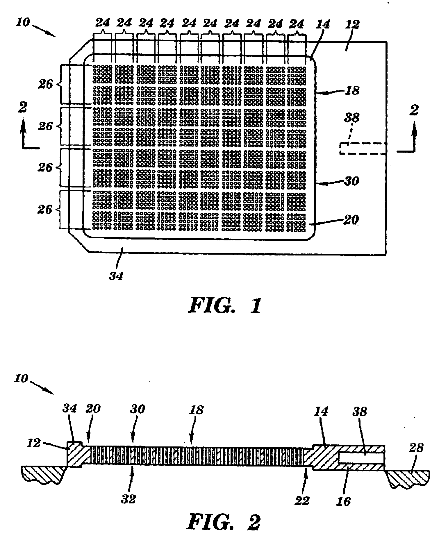
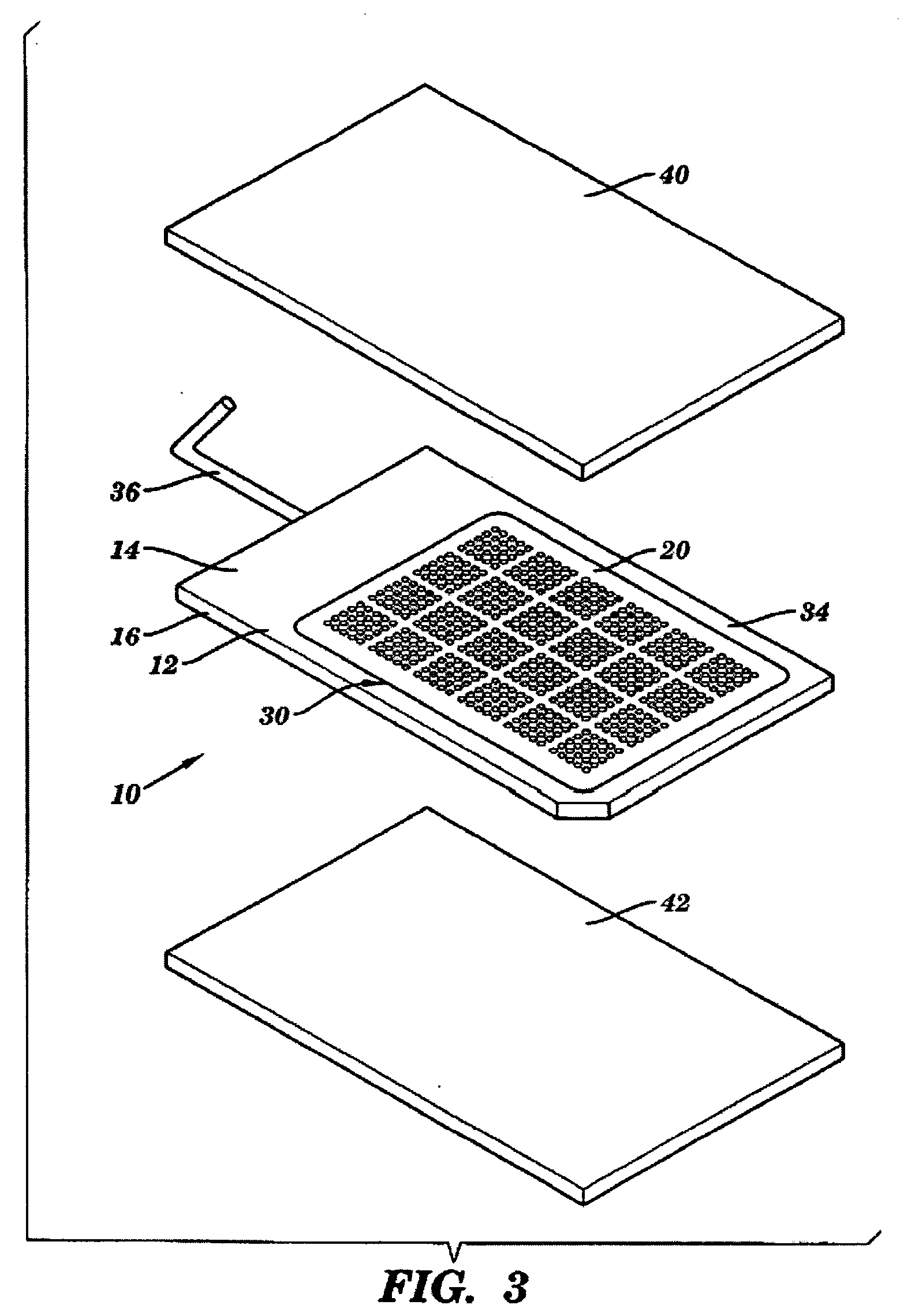
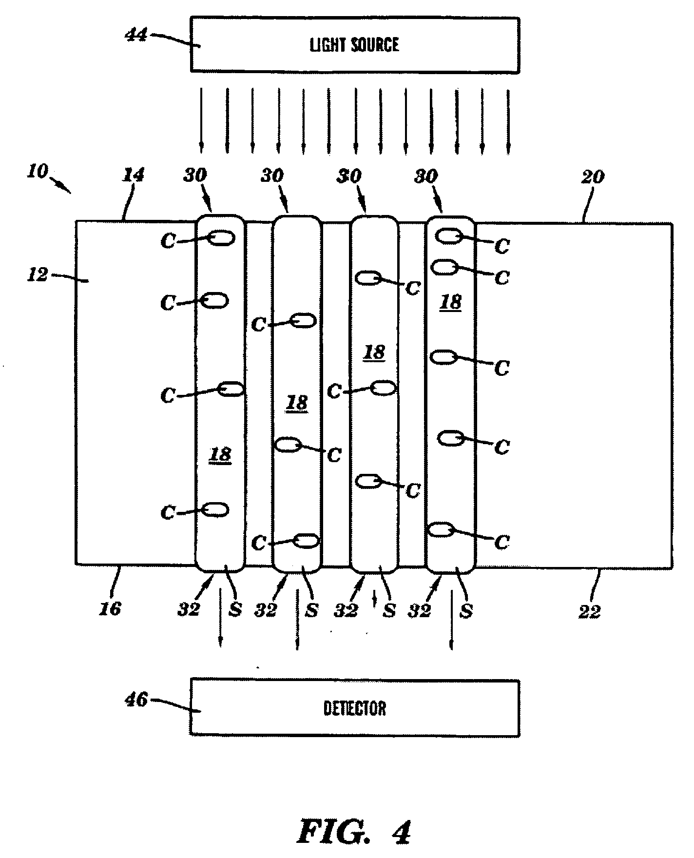
[0025] A testing apparatus 10 in accordance with one embodiment of the present invention is illustrated in FIG. 1. The testing apparatus 10 includes a testing plate 12 with a pair of opposing surfaces 14 and 16 (surface 16 is shown in FIG. 2) and a plurality of through holes 18. The through holes 18 are located in recessed portions 20 and 22 on each side of the testing plate 12. The through holes 18 are also arranged in groups 24 of at least two columns and two rows of holes 18 and in sets 26 of two or more groups of holes 18. The testing apparatus 10 provides a number of advantages including simplifying the procedure for loading samples of solution S into the holes 18 in the testing apparatus 10, simplifying the construction of the testing apparatus 10, and making the identification of a particular hole 18 filled easier for an operator.

[0026] Referring to FIGS. 1 and 2, the testing apparatus 10 includes the testing plate 12 which in this particular embodiment is made of a non-tran...


PUM

PropertyMeasurementUnit
volumeaaaaaaaaaa
diameteraaaaaaaaaa
distanceaaaaaaaaaa

Abstract

A spatially fixed library of mutated cells and a method for creating such a library. The library is created by creating a set of cells having a genetic diversity, causing the cells to multiply and express phenotypes, preparing a solution containing the cells diluted in a medium, populating a plurality of through-holes of a testing plate with the solution such that surface tension holds the solution in respective through-holes, and analyzing the phenotypes of the cells in the solution on a hole-by-hole basis. Cells expressing specified phenotypes may then be retrieved.

Description

CROSS REFERENCE TO RELATED APPLICATIONS [0001] This application is a divisional application of copending Ser. No. 10 / 223,893, filed Aug. 20, 2002, which is a continuation of U.S. Ser. No. 09 / 970,578 (issued as U.S. Pat. No. 6,436,632), which is a continuation of U.S. Ser. No. 09 / 528,085 (issued as U.S. Pat. No. 6,306,578), which is a continuation-in-part of U.S. Ser. No. 09 / 471,852 (abandoned), which is a continuation of U.S. Ser. No. 09 / 272,122 (issued as U.S. Pat. No. 6,027,873). Each of the patent applications described in this paragraph is hereby incorporated herein by reference.FIELD OF THE INVENTION [0002] This invention is related generally to a testing apparatus and, more particulary, to a multi-through hole testing plate for high throughout screening. BACKGROUND OF THE INVENTION [0003] Prior testing apparatuses have consisted of a testing plate with a pair of opposing surfaces and plurality of wells. The wells extend in from one of the opposing surfaces, but do not extend t...

Claims


Application Information

Patent Timeline
Patent Type & Authority Applications(United States)
IPC IPC(8): B01J19/00B01L3/00C40B60/14G01N35/00G01N35/10
CPCB01J19/0046G01N2035/00237B01J2219/00317B01J2219/00319B01J2219/0052B01J2219/00524B01J2219/00659B01J2219/00662B01J2219/00707B01L3/5025B01L3/5085B01L3/50857C40B60/14G01N35/1065B01J2219/00286B01J2219/00533B01J2219/00596B01J2219/00644B01L2300/0654B01L2300/0809B01L2300/161
Inventor SCHELLENBERGER, VOLKERLIU, AMY DEMING
Owner LIFE TECH CORP
Why Eureka
Try Eureka