Vehicle air conditioner

a technology for air conditioners and vehicles, applied in vehicle maintenance, vehicle cleaning, transportation and packaging, etc., can solve the problems of reducing the maximum cooling capacity in the condition of inside air suction mode, and the difficulty of providing enough space for the inside air inlet opening

Inactive Publication Date: 2005-03-17
DENSO CORP
View PDF2 Cites 2 Cited by
  • Summary
  • Abstract
  • Description
  • Claims
  • Application Information

AI Technical Summary

Benefits of technology

[0011] An object of the present invention is to provide a vehicle air conditi

Problems solved by technology

In such an arrangement, it is difficult to provide enough area of the inside air inlet opening 40B due to the outside air inlet opening 2

Method used


Image

  • Vehicle air conditioner
  • Vehicle air conditioner
  • Vehicle air conditioner

Examples


first embodiment

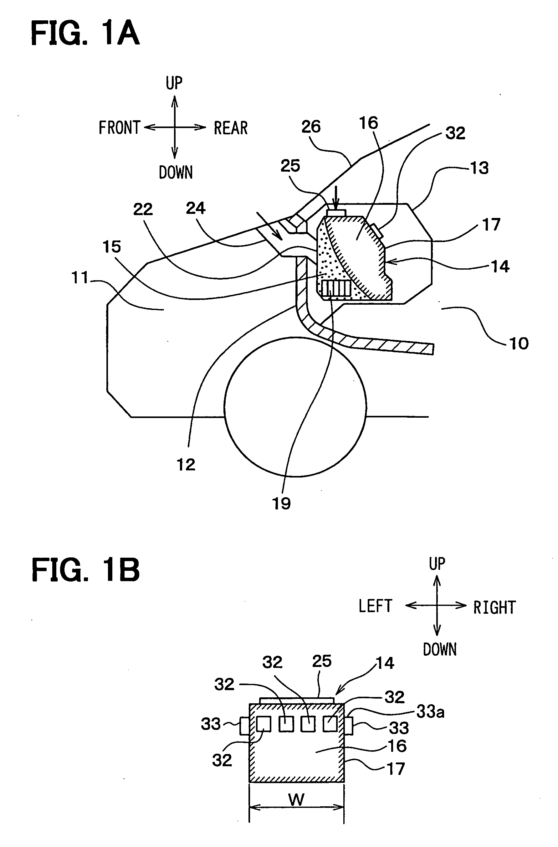
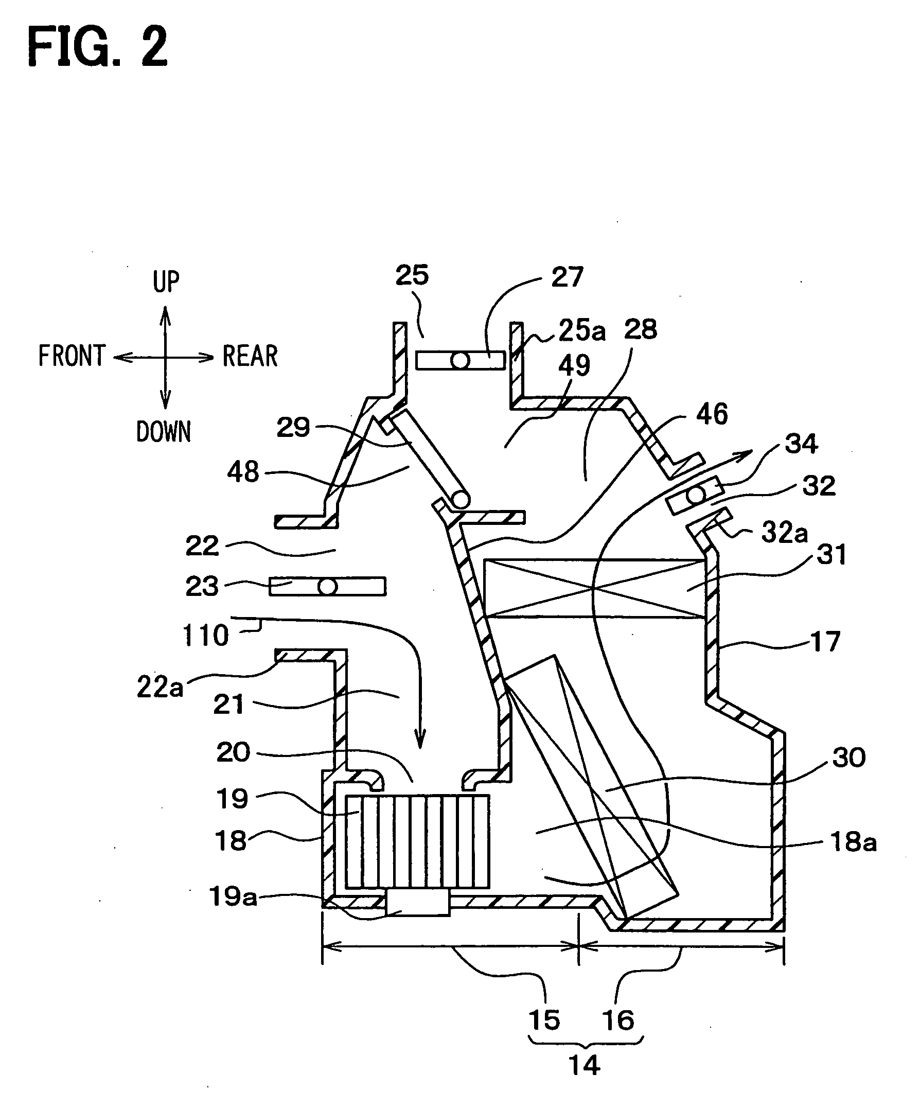
[0036] [First Embodiment]

[0037] As shown in FIG. 1A, a vehicle has a dashboard 12 to divide a passenger compartment 10 from an engine room 11. The passenger compartment 10 has an instrument panel 13, which is disposed in a front section of the passenger compartment 10. A vehicle air conditioner has an in-vehicle air conditioning unit 14. The in-vehicle air conditioning unit 14 is disposed at a vicinity of a central position of a vehicle width direction in the instrument panel 13.

[0038] The air conditioning unit 14 has a blower unit 15 and a conditioning body unit 16. The blower unit 15 blows air to the conditioning body unit 16. The conditioning body unit 16 adjusts temperature of the air blown from the blower unit 15, and blows the conditioned air to the passenger compartment 10. In detail, the air conditioning unit 14 has a single resinous conditioning housing 17 that has a box shape. The blower unit 15 and the conditioning body unit 16 are disposed directly adjacent to each othe...

second embodiment

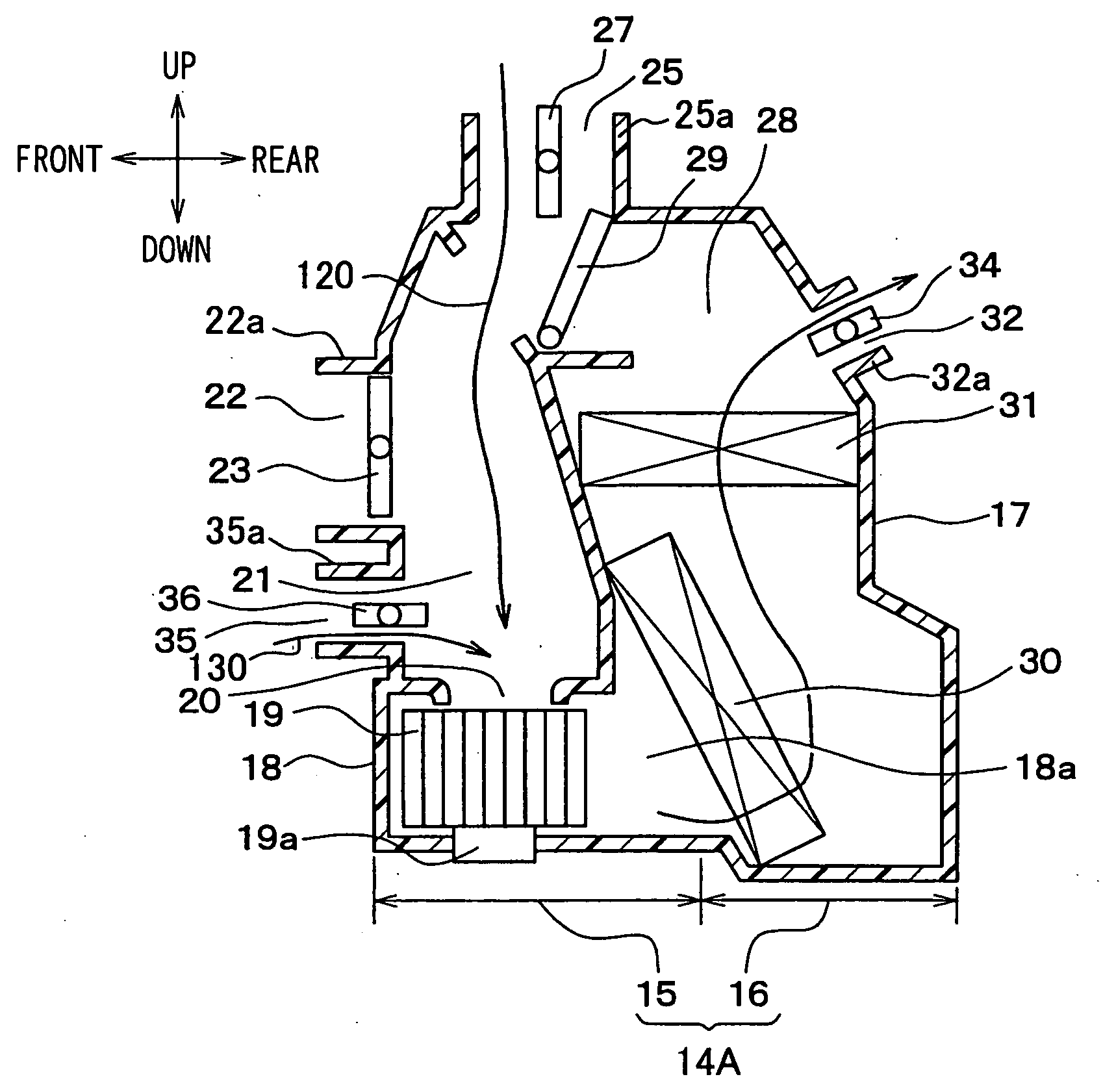
[0079] [Second Embodiment]

[0080]FIG. 5 shows another in-vehicle air conditioning unit 14A of the second embodiment during the inside air suction mode. The air conditioning unit 14A has an auxiliary inside air inlet 35a and an auxiliary inside air switching door 36 in addition to the components of the air conditioning unit 14 of the first embodiment.

[0081] The auxiliary inside air inlet 35a has an auxiliary inside air inlet opening 35 that is disposed below the outside air inlet opening 22 on the front sidewall of the conditioning housing 17 so that the auxiliary inside air inlet opening 35 is connected to the suction passage 21. The auxiliary inside air switching door 36, which consists of a butterfly valve, is rotatably disposed in the auxiliary inside air inlet opening 35 to open and close the auxiliary inside air inlet opening 35.

[0082] According to the second embodiment, the inside air is sucked to the suction passage 21 through the auxiliary inside air inlet opening 35 as sho...


PUM


Abstract

A vehicle air conditioner has an air conditioning unit. The unit has a blower unit and an heat exchanger. The unit has a defroster outlet opening and an outside air inlet opening. The unit also has a switching door. The unit has a first passage between the defroster opening and an upstream side of the blower unit, and a second passage between the defroster outlet opening and a downstream side of the heat exchanger. During an inside air suction mode, the outside air inlet opening is closed, and the first passage is opened and the second passage is closed by the switching door. Thus, inside air is sucked through the defroster outlet opening during the inside air suction mode.

Description

CROSS REFERENCE TO RELATED APPLICATIONS [0001] This application is based on Japanese Patent Application No. 2003-299902 filed on Aug. 25, 2003, the contents of which are incorporated herein by reference. BACKGROUND OF THE INVENTION [0002] 1. Field of the Invention [0003] The present invention relates to a vehicle air conditioner that has a downsized in-vehicle air conditioning unit. [0004] 2. Description of Related Art [0005]FIGS. 6A, 6B show an in-vehicle air conditioning unit of a vehicle air conditioner. The air conditioning unit has a blower unit 15A and a conditioning body unit 16A. The blower unit 15A blows air to the conditioning body unit 16A. The conditioning body unit 16A adjusts temperature of the air blown from the blower unit 15A, and blows the conditioned air to a passenger compartment of a vehicle. [0006] The conditioning body unit 16A is disposed in an instrumental panel 13, which is disposed in a front section of the passenger compartment 10, in a vicinity of a cent...

Claims


Application Information

Patent Timeline
IPC IPC(8): B60H1/00B60H1/34
CPCB60H1/00028B60H2001/00107B60H2001/00085B60H1/00849
Inventor SHINDOU, TOMOHIDEITOU, KOUJI
Owner DENSO CORP
Why Eureka
Try Eureka