Machining apparatus and machining line provided with same

a technology of machining equipment and machining line, which is applied in the direction of metal working equipment, metal-working machine components, manufacturing tools, etc., can solve the problems of not being able to perform the machining of the next workpiece by the first m/c, and not being able to mount successive workpieces in the first and second m/cs. to achieve the effect of performing more simply

Inactive Publication Date: 2005-03-17
AISIN AW CO LTD
View PDF3 Cites 7 Cited by
  • Summary
  • Abstract
  • Description
  • Claims
  • Application Information

AI Technical Summary

Benefits of technology

[0027] In one embodiment of the present invention, the machining apparatus is provided with a plurality of interchangeable machining tools for general-purpose machining, one of which tools is a workpiece holding jig. Accordingly, the mounting and removal of the workpiece can be executed simply and efficiently. If further provided with a tool changer, replacement of the workpiece holding jig can be executed more simply, and it is possible to mount and remove the workpiece even more simply and with an even greater degree of efficiency.
[0028] Because it is possible to temporarily hold the workpiece that has been machined in the machining apparatus, using the workpiece holding jig described above, there is no need to provide a temporary placement station for temporary placement of the workpiece in the vicinity of the machining apparatus. Further, the robot is no longer required to execute a temporary placement operation for the workpiece.
[0029] Moreover, because the machining line have a plurality of machining apparatuses arranged more closely in a line, since there is no need to provide space for temporary workpiec

Problems solved by technology

Accordingly, while a given workpiece for which machining has been completed by the first M/C is being processed by the second M/C, it is not possible to mount another workpiece in the first M/C.
As a result, machining of the next workpiece cannot be performed by the first M/C.
In addition, similarly, while a given workpiece that has been finished by the second M/C is being further machined by the nth M/C, it is not possible to mount successive workpieces in the first and second M/Cs.
Thus, there is substantial wasted time in the operation of this machining line, and the machining operations are not performed efficiently.
Thus, a long time is required for the completion of machining of a given number of workpieces.
Accordingly, there would still be substantial wasted time in the machining operation.
Moreover, the process requires the robot to execute mounting and removal o

Method used


Image

  • Machining apparatus and machining line provided with same
  • Machining apparatus and machining line provided with same
  • Machining apparatus and machining line provided with same

Examples


Embodiment Construction

[0040] Hereinafter, an embodiment of the invention will be explained with reference to the drawings.

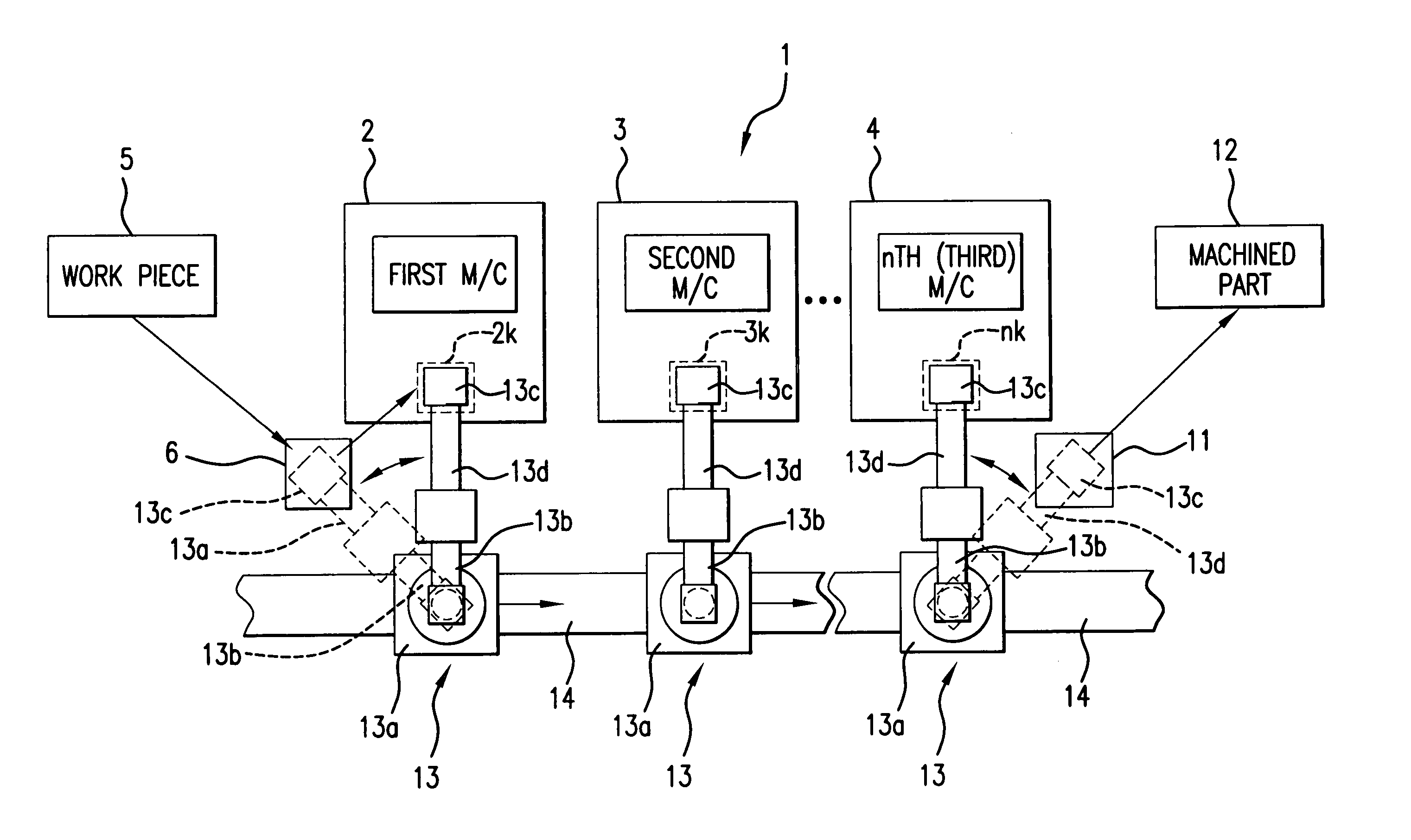
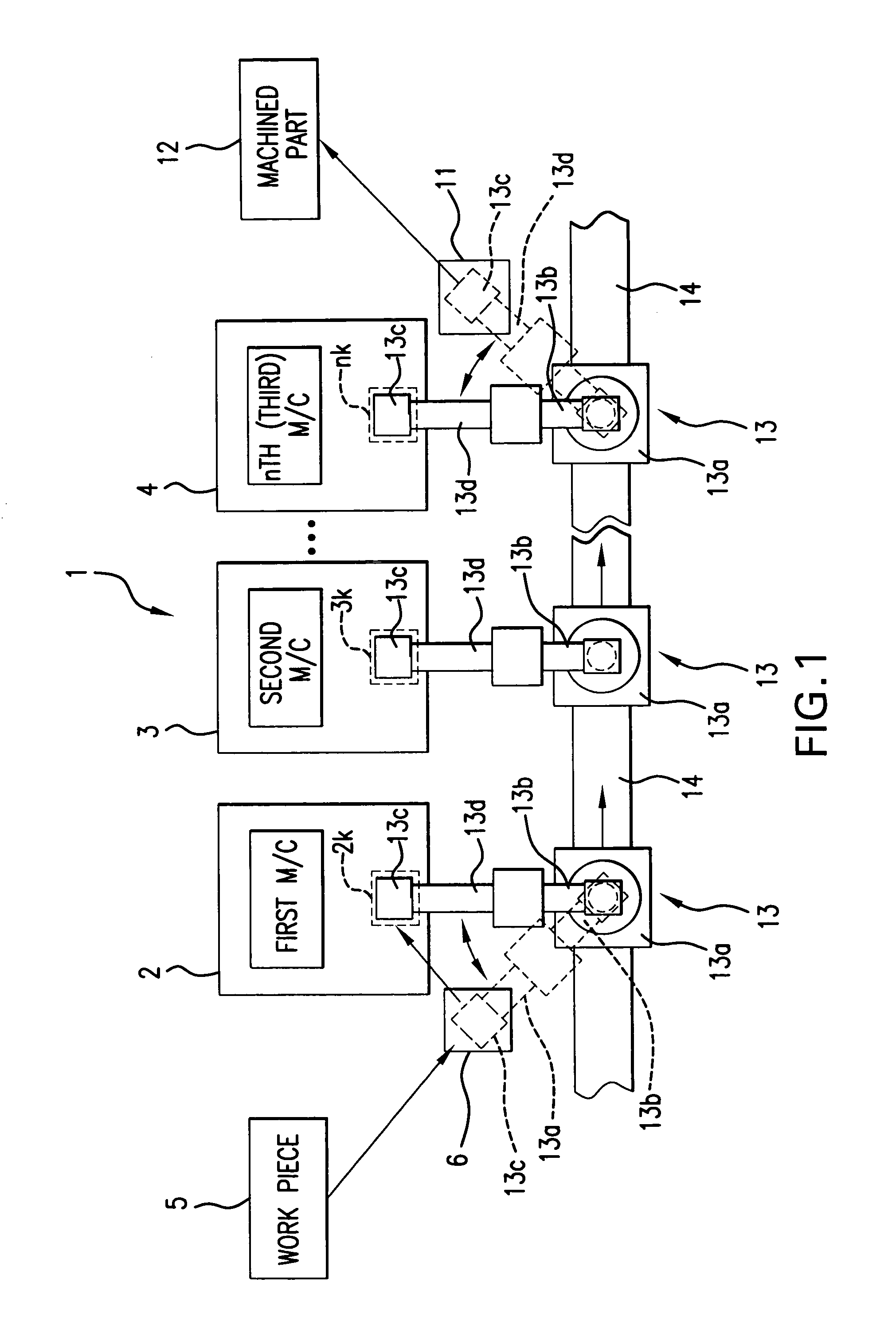
[0041]FIG. 1 shows an embodiment of a machining line in accordance with the present invention, wherein components that are the same as those of the machining line shown in FIG. 7, described previously, are denoted by the same reference numerals, and explanation thereof is omitted here.

[0042] As shown in FIG. 1, the machining line 1 of this embodiment is not provided with the temporary placement points 7, 8, 9 and 10 for the workpiece 5 that are included in the machining line 1 of FIG. 7.

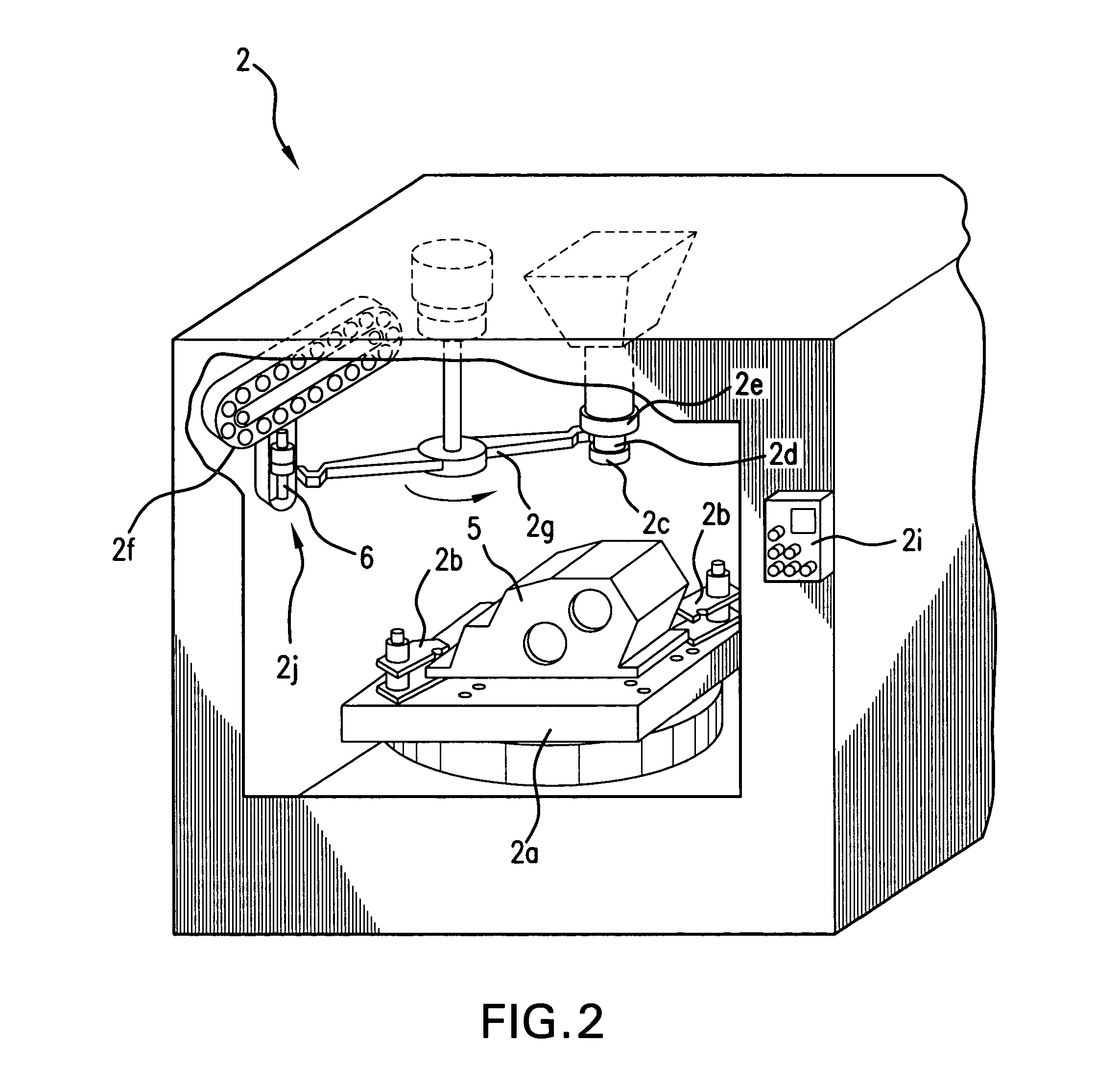
[0043]FIG. 2 shows an example of a first M / C 2. The first M / C 2 includes a table 2a for fixedly supporting the workpiece 5, a clamping device 2b for fixing the workpiece 5 to the table 2a, an adapter 2d which serves as a machining tool holder of the invention by which various tools 2c are-removably held; a spindle 2e for machining using the respective tools 2c fitted to the adapter 2d, a tool storag...


PUM


Abstract

A drill fitted to an adapter is used to drill a hole in a workpiece fixed on a table of a machining center. When the hole drilling is finished, the drill is removed from the adapter, and a workpiece holding jig is fitted to the adapter. Then, the adapter is lowered, and the workpiece holding jig takes the workpiece for which the hole drilling operation has been finished. Following this, the adapter is raised, and the workpiece is temporarily held in the machining center. Then, in this state, the next workpiece is mounted on the table of the machining center. Accordingly, by temporarily holding the workpiece, for which the hole drilling operation has been finished, in the machining center, mounting of the next workpiece is simplified.

Description

CROSS-REFERENCE TO RELATED APPLICATION [0001] This application claims, under 35 USC 119, priority of Japanese Patent Application No.2003-203166 filed on Jul. 29, 2003, the teachings of which are incorporated herein by reference in their entirety, including the specification, drawings and abstract. BACKGROUND OF THE INVENTION [0002] 1. Field of the Invention [0003] The invention relates to a machining apparatus for machining a workpiece, to a general-purpose apparatus, e.g., a “machining center”, that performs a variety of different types of machining operations by switching between various machining tools, and to a production line provided with a plurality of machining apparatuses. [0004] 2. Description of the Related Art [0005] Conventionally, a production line for automatic transmissions (hereinafter referred to as “A / T” or “A / Ts”) includes a machining line with plural machines for machining various types of workpieces, namely, components of the A / T. This machining line includes a...

Claims


Application Information

Patent Timeline
IPC IPC(8): B23Q3/155B23Q7/00B23Q7/04B23Q41/02
CPCB23Q7/045B23Q41/02Y10T29/49799Y10T483/10Y10T483/165Y10T29/49998Y10T29/49829
Inventor MURAI, KAZUTAKANOMA, SHIGETOANDOU, TOSHIYUKI
Owner AISIN AW CO LTD
Why Eureka
Try Eureka