Modular motion unit with tensioner

a technology of tensioner and module, applied in the field of precision positioners, can solve the problems of increasing design complexity and cost, difficult to change the range of motion and travel range of the robot, etc., and achieve the effect of convenient design and construction

Inactive Publication Date: 2005-03-24
NORDSON CORP
View PDF14 Cites 13 Cited by
  • Summary
  • Abstract
  • Description
  • Claims
  • Application Information

AI Technical Summary

Benefits of technology

[0005] Embodiments of the present invention address these and other problems of the prior art by providing a modula

Problems solved by technology

This can increase design complexity and costs.
Additionally, it can be very difficult to change th

Method used


Image

  • Modular motion unit with tensioner
  • Modular motion unit with tensioner
  • Modular motion unit with tensioner

Examples


Embodiment Construction

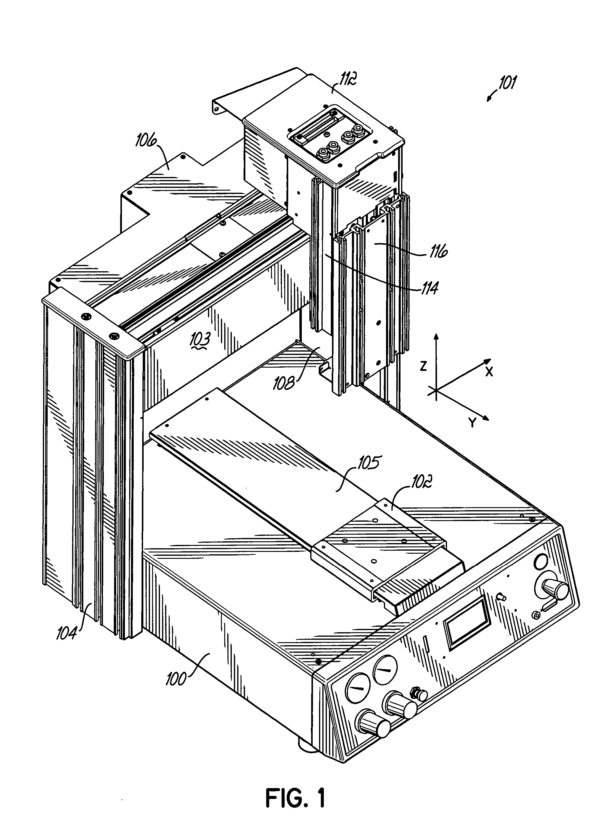
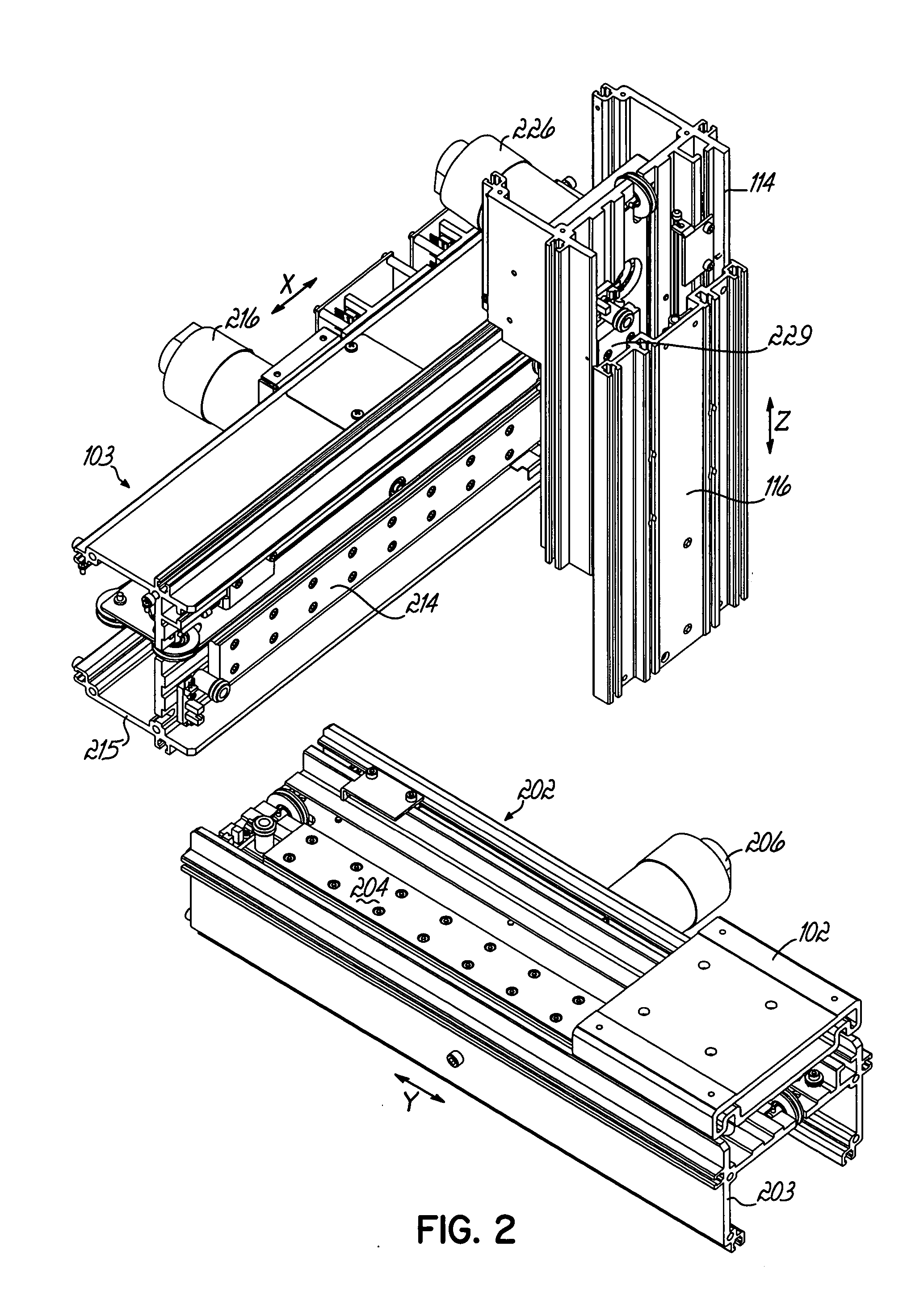
[0018]FIG. 1 illustrates a positioner unit, or robot, that includes three modular motion units assembled on a frame. FIG. 2 illustrates the same arrangement of the modular motion units without the frame structure being depicted. While precision positioner units of various sizes and capabilities are contemplated by the present invention, one exemplary positioner unit operates at acceleration forces of approximately ¼ g, provides positional accuracy to about 5 mils and positional repeatability of about 2 mils.

[0019] Referring to FIGS. 1 and 2, the positioner unit 101 includes a base 100, that in this instance houses the computer control assemblies and other electronic circuitry of the robot. With respect to the modular motion units, the base 100 provides a place to mount one of the modular motion units. Although obscured by the base 100 and the splash guard 105, in this drawing, the modular motion unit is oriented so as to extend from the front of the base 100 to its rear and allows ...


PUM


Abstract

A precision positioning device, such as a robot, decouples the different axes of motion by utilizing a modular motion unit for each different axis of motion. Each modular motion unit includes a base structure, a linear guide, a carriage, a drive motor, and a cable to convert the torque of the drive motor into useful, controlled carriage movement. The parts and sub-assemblies of each modular motion unit are interchangeable without concern about the ultimate orientation of the unit. To assemble the units into a robot, the modular motion units are attached to an underlying frame structure to provide computer-controlled movement over a designated physical work space. Re-tensioning of a drive cable within the modular motion unit is accomplished without requiring the operator to have special training or tools. One end of the drive cable is attached to a tensioner that is releasably locked into place. When the tensioner is released, a spring operates to move the tensioner, and the cable, to a properly tensioned position.

Description

CROSS REFERENCE TO RELATED APPLICATIONS [0001] This application claims the benefit of U.S. Provisional Application No. 60 / 504,584, filed Sep. 19, 2003, the disclosure of which is hereby incorporated by reference herein in its entirety.FIELD OF THE INVENTION [0002] This invention relates generally to precision positioners and, more particularly, to computer controlled positioning tables. BACKGROUND OF THE INVENTION [0003] Robots that move in the X, Y and Z axes are used in many technological fields to automate repetitive tasks, like those encountered on a production line. One particular type of robot, or precision positioning unit, of this nature involves a carriage that moves in a linear fashion over a range of positions under control of a computer. Conventionally, these robots include, for each axis of motion, a linear guide on a base structure that is interconnected with base structures for the other axes. A respective drive unit, such as a chain, belt, gear, ball screw or lead sc...

Claims


Application Information

Patent Timeline
IPC IPC(8): B25J9/02B25J9/10F16H19/06
CPCB25J9/026B25J9/1045Y10T74/18848F16H2019/0686F16H19/0672
Inventor MEIER, MARK S.
Owner NORDSON CORP
Why Eureka
Try Eureka