Multi-polar rotary machine

Inactive Publication Date: 2005-03-24
JAPAN SERVO CO LTD
View PDF13 Cites 46 Cited by
  • Summary
  • Abstract
  • Description
  • Claims
  • Application Information

AI Technical Summary

Benefits of technology

Accordingly, an object of the present invention is to provide a motor wherein an output of the motor is increased by reducing the magnetic reluctance of the paths in the axial direction of the motor, and b

Problems solved by technology

In general, each of the rotor and the stator of the motor is formed by laminating a plurality of silicon steel plates, and each silicon steel plate is coated with an anti-corrosion film, so that a gap is formed between lamin

Method used


Image

  • Multi-polar rotary machine
  • Multi-polar rotary machine
  • Multi-polar rotary machine

Examples


first embodiment

A hybrid stepping motor of a first embodiment according to the present invention will be explained. Parts of the motor which are similar to corresponding parts of the conventional motor shown in FIG. 26 and FIG. 27 have been given corresponding reference numerals and need not be further redescribed.

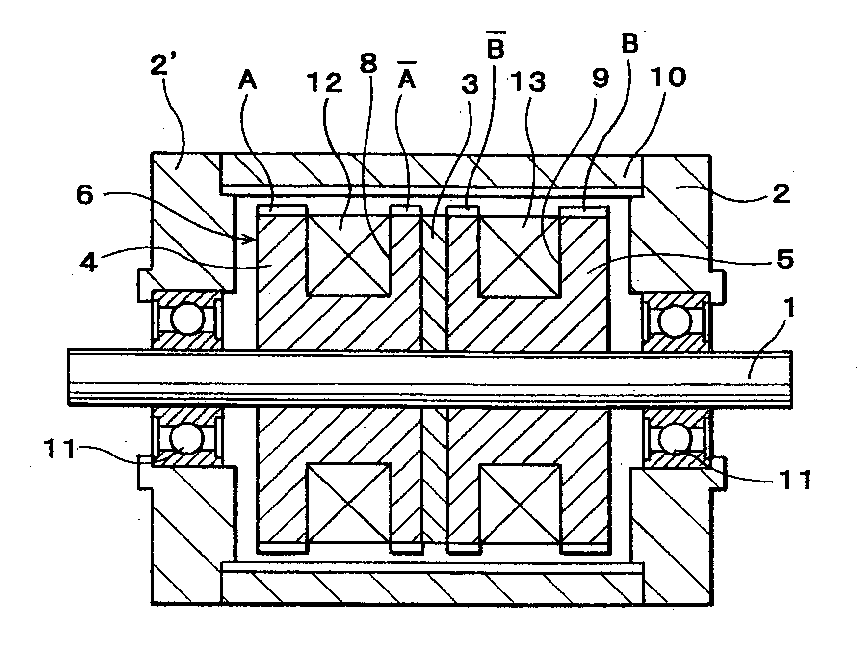
As shown in FIG. 1, a multi-polar rotary machine, such as an outer rotor type two-phase hybrid stepping motor of an embodiment of the present invention comprises a stator 6 and a cylindrical outer rotor 10 arranged concentrically with the stator 6 and with an air gap therebetween.

Said stator 6 has two splitted stator elements 4,5 and a ring shaped permanent magnet 3 held between the stator elements 4, 5 and magnetized so as to form N and S poles in the axial direction of the stator 6, a plurality of small stator teeth A and {overscore (A)} separated in the axial direction of the stator 6 from each other and formed on the outer peripheral surface of one of the splitted stator elements 4...

second embodiment

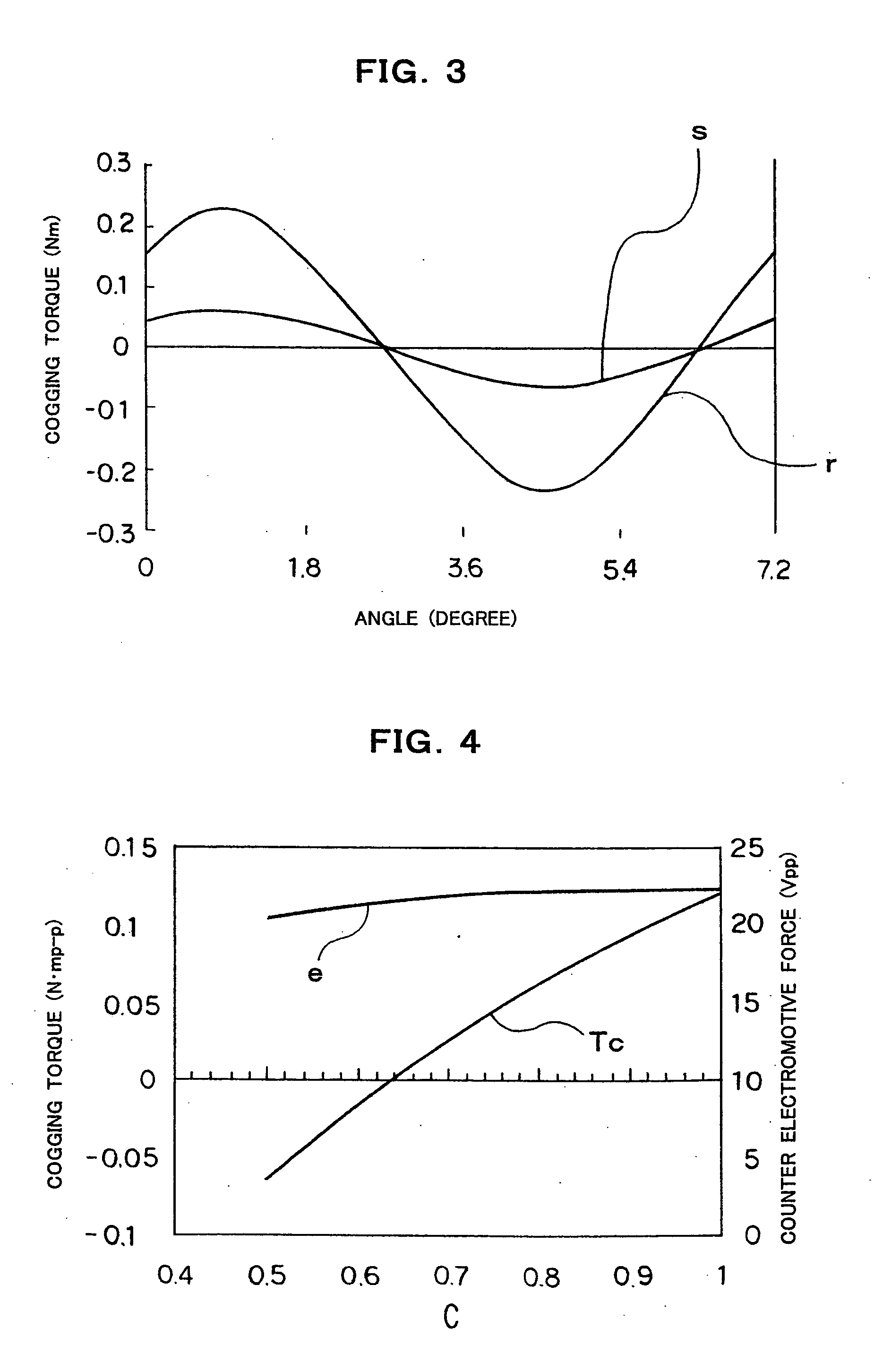
The powder of soft magnetic material itself is high in electric resistance, so that the eddy current loss in the motor can be reduced, and accordingly it is effective to use for the higher speed motor. In the present invention, a ratio C of a thickness of the small stator teeth {overscore (A)} in the axial direction of the stator to a thickness of the small stator teeth A in the axial direction of the stator (stack ratio) is set to a value smaller than 1, preferably 0.5 to 0.8 so as to equalize substantially in mean permeance both small stator teeth A and {overscore (A)} to each other, and a ratio C of a thickness of the small stator teeth {overscore (B)} in axial direction of the stator to a thickness of the small stator teeth B in the axial direction of the stator (stack ratio) is set to a value smaller than 1, preferably 0.5 to 0.8 so as to equalize substantially in mean permeance both small stator teeth {overscore (B)} and B to each other.

FIG. 4 is a diagram showing a characteri...


PUM


Abstract

A multi-polar rotary machine comprises a and a cylindrical outer rotor arranged concentrically with the stator and with an air gap therebetween. The stator has two splitted stator elements and a ring shaped permanent magnet held between the stator elements and magnetized so as to form N and S poles in the axial direction of the stator. Small axially separated stator teeth A and {overscore (A)} and {overscore (B)} and B are formed on the outer peripheral surface of the splitted stator elements. Stator windings for A phase and B phase are wound around the respective stator elements. The small stator teeth A, {overscore (A)}, {overscore (B)} and B are circumferentially shifted from corresponding small rotor teeth by a ¼ pitch of the small stator teeth, respectively. Each of the stator and rotor is formed of pressed powder consisting of soft magnetic material, and of resin and/or inorganic material. A ratio of a thickness of the small stator teeth {overscore (A)} in the axial direction of the stator to a thickness of the small stator teeth A in the axial direction of the stator or a ratio of a thickness of the small stator teeth {overscore (B)} in the axial direction of the stator to a thickness of the small stator teeth B in the axial direction of the stator is set to a value smaller than 1 so as to equalize substantially in mean permeance both small stator teeth A and {overscore (A)} or {overscore (B)} and B to each other.

Description

BACKGROUND OF THE INVENTION 1. Field of the Invention The present invention relates to a multi-polar rotary machine, and more particularly, to a typical hybrid type stepping motor capable of increasing an output and reducing cogging torque for use in an office automation (OA) apparatus or a fully automatic (FA) equipment. 2. Description of the Prior Art A variable•reluctance (VR) type stepping motor having a rotor using no permanent magnet, a permanent magnet (PM) type stepping motor having a rotor composed of a permanent magnet, and a hybrid (HB) type stepping motor formed by mixing the variable•reluctance type stepping motor and the permanent magnet type stepping motor have been proposed. The permanent magnet type stepping motor and the hybrid type stepping motor are capable of reducing in size and accordingly are used in a relatively small industrial machine. Especially, the hybrid type stepping motor is high in precision and torque and is small in step angle, and accordingly...

Claims


Application Information

Patent Timeline
IPC IPC(8): H02K37/18H02K37/20
CPCH02K37/20H02K37/18
Inventor OHNISHI, KAZUOOHIWA, SHOJIMOTEGI, YASUAKI
Owner JAPAN SERVO CO LTD
Why Eureka
Try Eureka