Multi-Polar Rotary Machine

a rotary machine and multi-polar technology, applied in the field of multi-polar rotary machines, can solve the problems of large vibration in the motor when it is rotated, unavoidable gap formation between laminated silicon steel plates, etc., and achieve the effects of reducing the magnetic reluctance of the path, reducing the cogging torque of the motor, and increasing the magnetic flux interlinking winding

Inactive Publication Date: 2007-04-26
JAPAN SERVO CO LTD
View PDF9 Cites 7 Cited by
  • Summary
  • Abstract
  • Description
  • Claims
  • Application Information

AI Technical Summary

Benefits of technology

[0024] Accordingly, an object of the present invention is to provide a motor wherein an output of the motor is increased by reducing the magnetic reluctance of the paths in the axial direction of the motor, and balancing magnetic paths of A, A, B and B to one another so that the magnetic flux interlinkaging the winding is increased, and wherein the cogging torque of the motor is reduced.

Problems solved by technology

In general, each of the rotor and the stator of the motor is formed by laminating a plurality of silicon steel plates, and each silicon steel plate is coated with an anti-corrosion film, so that a gap is formed between laminated silicon steel plates unavoidably.
The magnitude of the cogging torque r is about 0.5 Nm and increased compared with the normal motor of similar dimension, thereby causing a large vibration in the motor when it is rotated.

Method used


Image

  • Multi-Polar Rotary Machine
  • Multi-Polar Rotary Machine
  • Multi-Polar Rotary Machine

Examples


first embodiment

[0070] A hybrid stepping motor of a first embodiment according to the present invention will be explained. Parts of the motor which are similar to corresponding parts of the conventional motor shown in FIG. 26 and FIG. 27 have been given corresponding reference numerals and need not be further redescribed.

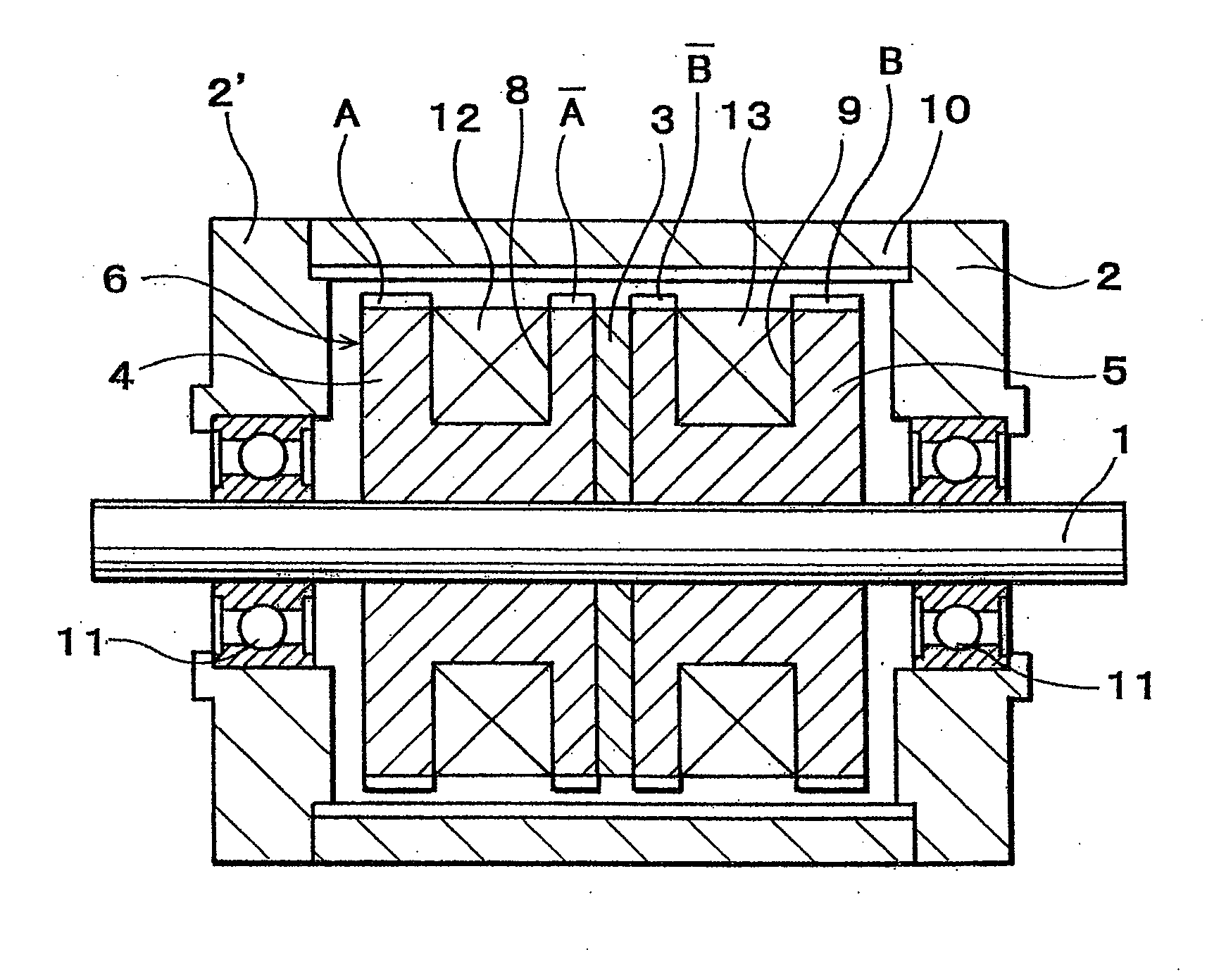
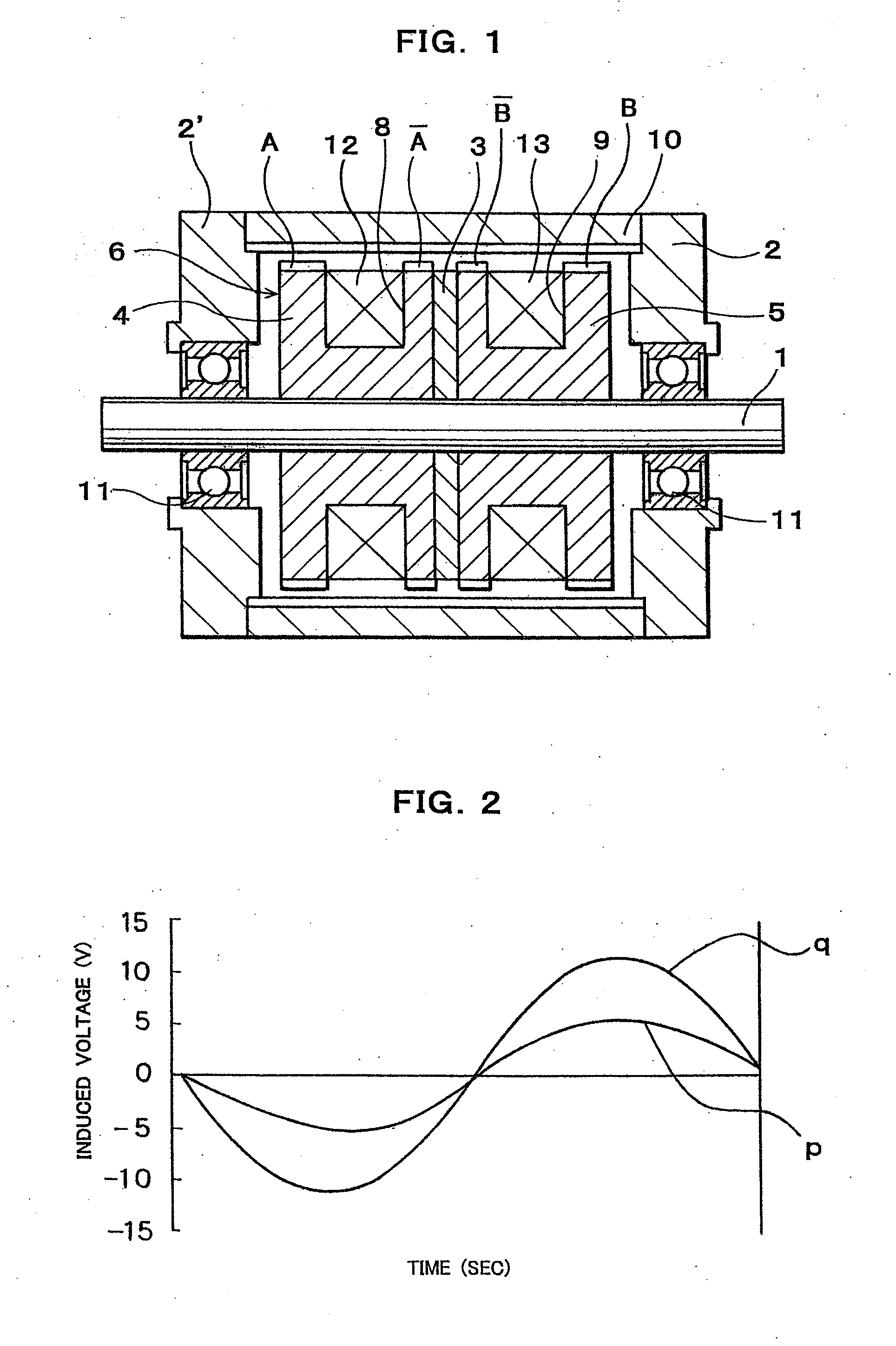
[0071] As shown in FIG. 1, a multi-polar rotary machine, such as an outer rotor type two-phase hybrid stepping motor of an embodiment of the present invention comprises a stator 6 and a cylindrical outer rotor 10 arranged concentrically with the stator 6 and with an air gap therebetween.

[0072] Stator 6 has two splitted stator elements 4,5 and a ring shaped permanent magnet 3 held between the stator elements 4, 5 and magnetized so as to form N and S poles in the axial direction of the stator 6, a plurality of small stator teeth A and A separated in the axial direction of the stator 6 from each other and formed on the outer peripheral surface of one of the spaced stator elements 4, ...

second embodiment

[0079] In the present invention, a ratio C of a thickness of the small stator teeth A in the axial direction of the stator to a thickness of the small stator teeth A in the axial direction of the stator (stack ratio) is set to a value smaller than 1, preferably 0.5 to 0.8 so as to equalize substantially in mean permeance both small stator teeth A and A to each other, and a ratio C of a thickness of the small stator teeth B in axial direction of the stator to a thickness of the small stator teeth B in the axial direction of the stator (stack ratio) is set to a value smaller than 1, preferably 0.5 to 0.8 so as to equalize substantially in mean permeance both small stator teeth B and B to each other.

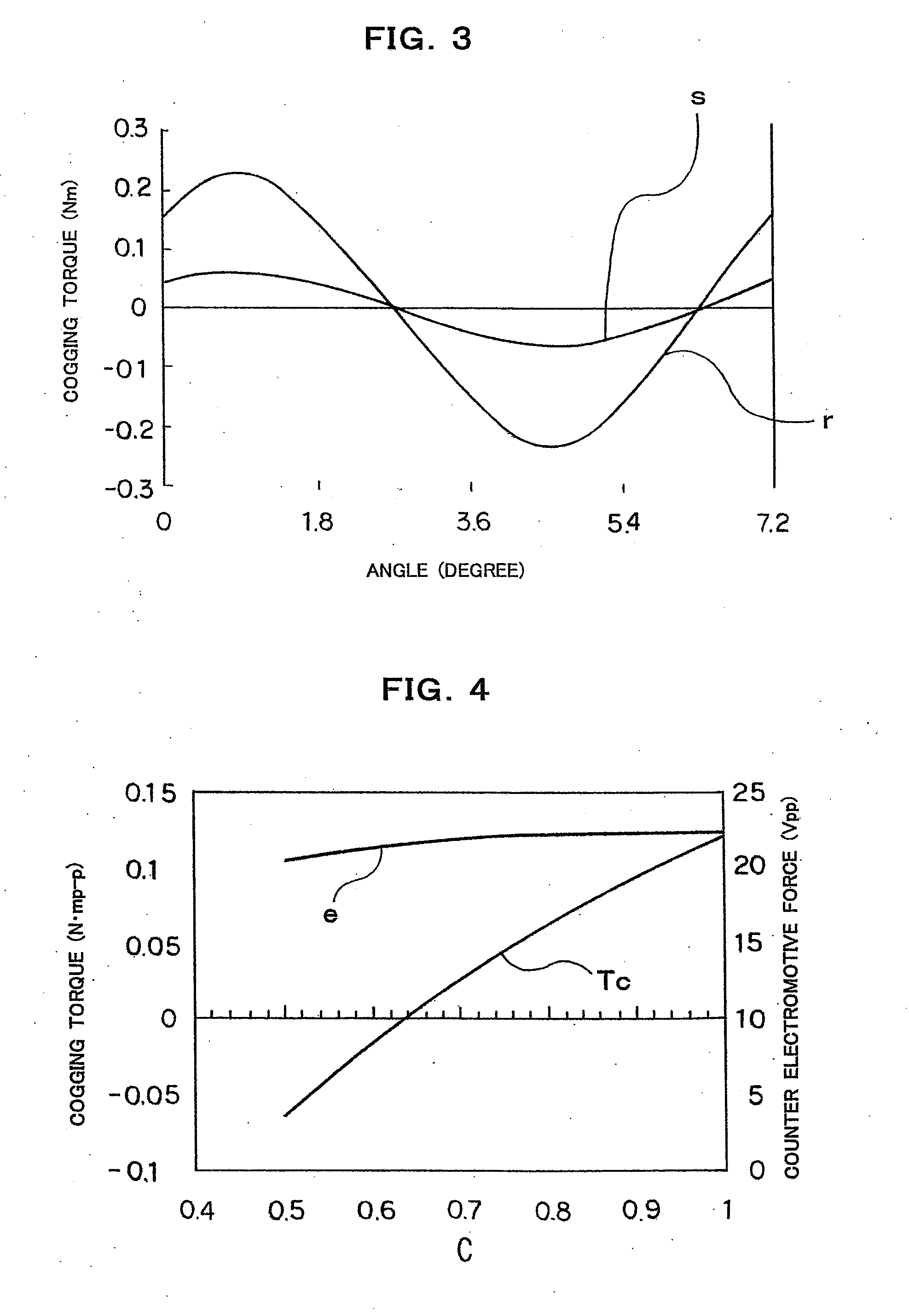
[0080]FIG. 4 is a diagram showing a characteristic feature of the cogging torque Tc and the counter electromotive force e with respect to the stack ratio C of the stator core. In FIG. 4, the abscissa shows the ratio C and the ordinate shows the counter electromotive force e and the cogging ...

third embodiment

[0082] In the present invention, the small rotor teeth of the rotor 10 are arranged with vernier pitch different from the regular pitch of 7.2°, that is 360° / 50 in case that the number of the small rotor teeth is 50, for example. The small rotor teeth of the vernier pitch are divided into two, for example, and a gap is formed between divided small rotor teeth so that the divided small rotor teeth are arranged axisymmetrically, in order to eliminate an unbalance magnetic attractive force in the radial direction of the rotor.

[0083] In this case, the small stator teeth A, A, B and B are circumferentially shifted from the small rotor teeth by 0°, 180°, 90° and 270° in electrical angle, respectively, as shown in FIG. 6.

[0084] Further, in the other embodiment of present invention, the same effect can be obtained by arranging the small stator teeth of the stator with vernier pitch, instead of the small rotor teeth of the rotor.

[0085] (Equivalent Magnetic Circuit of Motor)

[0086] In order...


PUM


Abstract

A multi-polar rotary machine comprises a cylindrical outer rotor arranged concentrically with the stator and with an air gap therebetween. The stator has two spaced stator elements and a ring shaped permanent magnet held between the stator elements and magnetized so as to form N and S poles in the axial direction of the stator. Small axially separated stator teeth A and A and B and B are formed on the outer peripheral surface of the spaced stator elements. Stator windings for A phase and B phase are wound around the respective stator elements. The small stator teeth A, A, B and B are circumferentially shifted from corresponding small rotor teeth by a ¼ pitch of the small stator teeth, respectively. Each of the stator and rotor is formed of pressed powder comprising a soft magnetic material at least one of a resin and an inorganic material.

Description

CROSS REFERENCE TO RELATED APPLICATION [0001] This application is a divisional of U.S. patent application Ser. No. 10 / 939,873 filed on Sep. 13, 2004, the entire contents of which is hereby expressly incorporated by reference into the present application.BACKGROUND OF THE INVENTION [0002] 1. Field of the Invention [0003] The present invention relates to a multi-polar rotary machine, and more particularly, to a typical hybrid type stepping motor capable of increasing an output and reducing cogging torque for use in an office automation (OA) apparatus or a fully automatic (FA) equipment. [0004] 2. Description of the Prior Art [0005] A variable • reluctance (VR) type stepping motor having a rotor using no permanent magnet, a permanent magnet (PM) type stepping motor having a rotor composed of a permanent magnet, and a hybrid (HB) type stepping motor formed by mixing the variable • reluctance type stepping motor and the permanent magnet type stepping motor have been proposed. The permane...

Claims


Application Information

Patent Timeline
Patent Type & Authority Applications(United States)
IPC IPC(8): H02K37/14H02K21/12H02K37/18H02K37/20
CPCH02K37/18H02K37/20
Inventor OHNISHI, KAZUOOHIWA, SHOJIMOTEGI, YASUAKI
Owner JAPAN SERVO CO LTD
Why Eureka
Try Eureka