Cable location continuously determining apparatus, cable location continuously determining method, and cable location continuously determining program

a technology of cable location and location, applied in the direction of electric/magnetic detection, instruments, and using reradiation, can solve the problem of discrepancies in cable location, and achieve the effect of high precision

Inactive Publication Date: 2005-03-24
NTT INFRASTRUCTURE NETWORK
View PDF11 Cites 26 Cited by
  • Summary
  • Abstract
  • Description
  • Claims
  • Application Information

AI Technical Summary

Benefits of technology

[0016] With this structure, it is possible to obtain the location data with high pre

Problems solved by technology

Therefore, a problem arises in that only the d

Method used


Image

  • Cable location continuously determining apparatus, cable location continuously determining method, and cable location continuously determining program
  • Cable location continuously determining apparatus, cable location continuously determining method, and cable location continuously determining program
  • Cable location continuously determining apparatus, cable location continuously determining method, and cable location continuously determining program

Examples


Embodiment Construction

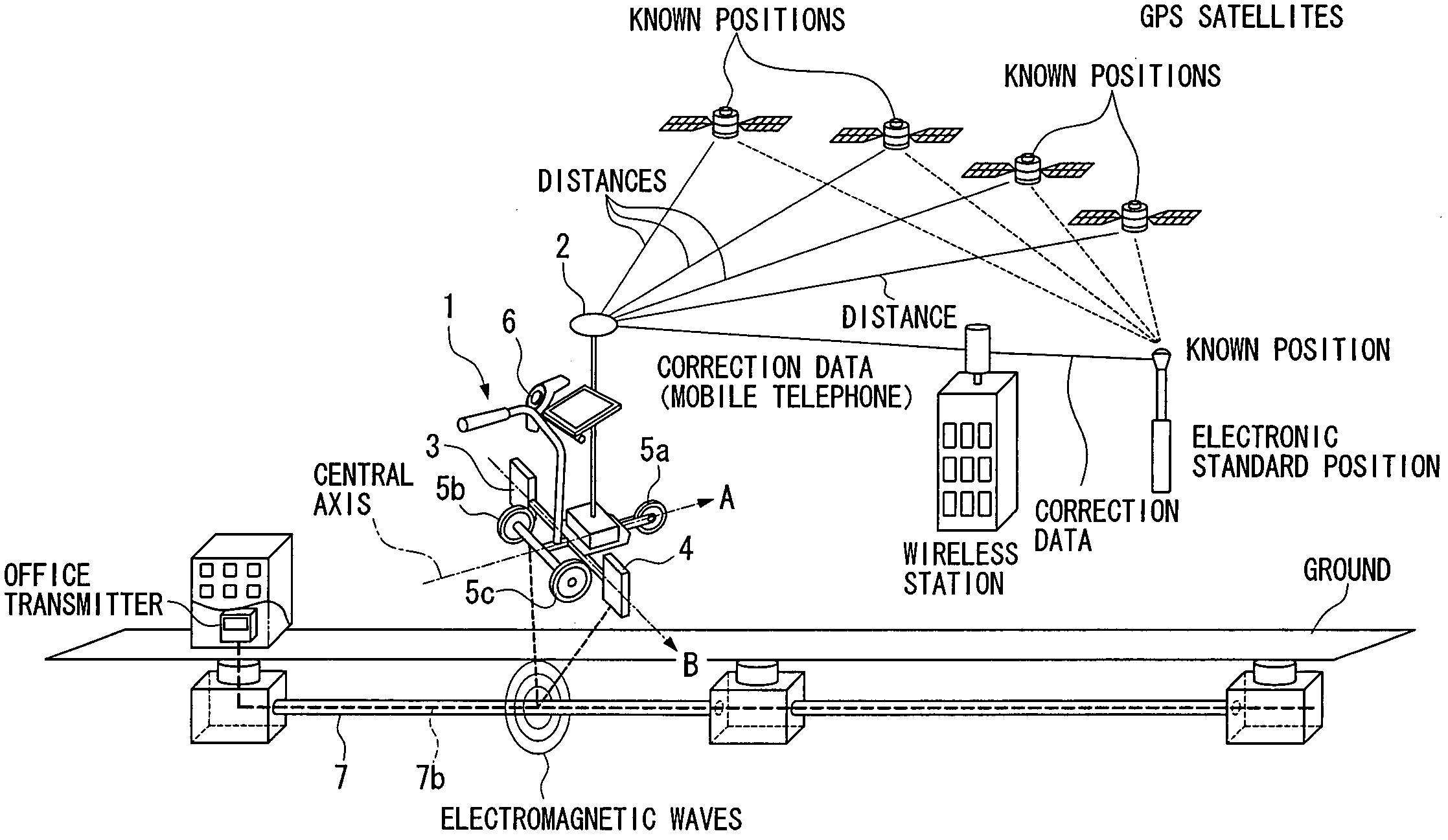
[0022] First, the mechanism for determining the location of a cable according to an embodiment of the present invention will be explained with reference to FIG. 1. FIG. 1 is a diagram for explaining the mechanism for determining the location of a cable.

[0023] As shown in FIG. 1, a cable location continuously determining apparatus 1 is provided with wheels 5a, 5b, and 5c which function as a moving mechanism, thereby allowing the cable location continuously determining apparatus 1 to move along the direction of arrow A shown in FIG. 1. When the location of a cable 7 which is buried in the ground is determined by using the cable location continuously determining apparatus 1, the cable location continuously determining apparatus 1 is moved along the cable 7.

[0024] The cable location continuously determining apparatus 1 is also provided with a GPS antenna 2, and obtains location data including latitude and longitude of a measurement standard position using an RTK-GPS (Real-Time Kinetic...


PUM


Abstract

An apparatus is provided that can continuously determine the location at which a cable is buried. The location data of a measurement standard position is acquired by RTK-GPS. The azimuth of the moving direction of the cable location continuously determining apparatus is calculated using the location data. Electromagnetic waves from a metallic wire are received by two electromagnetic signal receiving sections whose locations in the horizontal plane are different from each other, and distances from the measurement standard position to a cable in a measurement base line direction and in the vertical downward direction are calculated using the received electromagnetic signals. The depth of the cable is calculated using the distance in the vertical downward direction. The plane location data of the cable is calculated using the azimuth of the moving direction, the location data of the measurement standard position, and the distance in the measurement base line direction.

Description

BACKGROUND OF THE INVENTION [0001] 1. Field of the Invention [0002] The present invention relates to a cable location continuously determining apparatus, a cable location continuously determining method, and a cable location continuously determining program which determine the location of a cable buried in the ground. [0003] Priority is claimed on Japanese Patent Application No. 2003-330245 filed Sep. 22, 2003, the contents of which are incorporated herein by reference. [0004] 2. Description of Related Art [0005] When performing construction work to repair a cable which has already been buried or when performing construction work to bury a new cable, it is necessary to determine the location at which an existing cable is buried in order to prevent the existing cable from being damaged. Thus, in the past, various research relating to techniques of determining the location of a cable have been made, and their outcomes have been reported. [0006] For example, in Japanese Unexamined Pate...

Claims


Application Information

Patent Timeline
IPC IPC(8): G01V3/08G01V3/15
CPCG01V3/15
Inventor NAKANISHI, SHINSUKEOTSUKI, KAZUHIRONISHIWAKI, KENHIDAKA, KAZUTOSHI
Owner NTT INFRASTRUCTURE NETWORK
Why Eureka
Try Eureka