Apparatus for shaping the radiation pattern of a planar antenna near-field radar system

a radar system and antenna technology, applied in the direction of reradiation, individual energised antenna arrays, instruments, etc., can solve the problems of limiting system performance, excluding approaches, and not being well suited to wide-area-of-coverage applications, etc., to achieve simple and inexpensive manufacturing

Active Publication Date: 2005-03-24
APTIV TECH LTD
View PDF2 Cites 34 Cited by
  • Summary
  • Abstract
  • Description
  • Claims
  • Application Information

AI Technical Summary

Benefits of technology

[0004] The present invention is directed to an improved near-field radar apparatus including a fixed beam planar radar antenna and a radiation pattern adaptation device disposed substantially at the near-field boundary of the antenna. The adaptation device comprises a plurality of dielectric elements that individually constitute or approximate different surface portions of an idealized imaginary quasi-spherical or quasi-cylindrical radome reflector. The dielectric elements can be maintained physically separate or combined about the diffraction point of the antenna elements to form a single dielectric element. The dielectric elements may be mounted on a radome that is otherwise transparent to the radiation pattern, or otherwise suspended at or near the near-field boundary of the antenna. The dielectric elements may be simple and inexpensive to manufacture, and do not significantly impact the package size of the radar apparatus.

Problems solved by technology

Short-range obstacle detection for vehicle back-up and parking aid functions can be achieved with a wide-angle radar system, but cost and packaging considerations force design constraints that tend to limit the system performance.
For example, cost considerations effectively rule out the use of multiple transceivers for meeting wide zone-of-coverage requirements, and both packaging and cost considerations effectively require the use of planar transmit and receive antennas, which in general are not well-suited to wide zone-of-coverage applications.
However, such approaches are usually ruled out due to cost and packaging considerations.

Method used


Image

  • Apparatus for shaping the radiation pattern of a planar antenna near-field radar system
  • Apparatus for shaping the radiation pattern of a planar antenna near-field radar system
  • Apparatus for shaping the radiation pattern of a planar antenna near-field radar system

Examples


Embodiment Construction

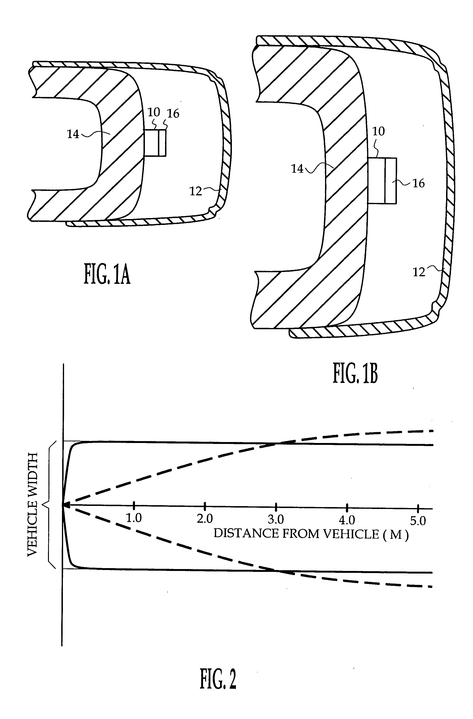
[0014] The radar system of the present invention applies in general to the use of a fixed beam radar sensor in applications requiring a wide-angle zone-of-coverage. The invention is illustrated herein in the context of a vehicle back-up and parking aid, but is applicable to other vehicle systems such as frontal or side object detection systems, and also to non-vehicle systems.

[0015]FIGS. 1A-1B depict a bumper-mounted back-up aid mechanization where a fixed beam radar sensor 10 is concealed behind a plastic fascia 12 surrounding the bumper frame 14. The adaptation device of the present invention is designated by the reference numeral 16, and is disposed in front of the radar sensor 10. While FIGS. 1A-1B show the adaptation device 16 as being supported on the radar sensor 10, it should be understood that the adaptation device 16 may be supported independent of the radar sensor 10—for example, by the bumper frame 14 or the plastic fascia 12. In the illustrated back-up aid application,...


PUM


Abstract

A near-field radar apparatus includes a fixed beam planar radar antenna and a radiation pattern adaptation device disposed substantially at the near-field boundary of the antenna. The adaptation device comprises a plurality of dielectric elements that individually constitute or approximate different surface portions of an idealized quasi-spherical or quasi-cylindrical radome reflector. The dielectric elements can be maintained physically separate or combined about the diffraction point of the antenna to form a single dielectric element. The dielectric elements may be mounted on a radome that is otherwise transparent to the radiation pattern, or otherwise suspended at or near the near-field boundary of the antenna.

Description

TECHNICAL FIELD [0001] The present invention is directed to near-field radar obstacle detection for vehicles, and more particularly to apparatus for shaping the radar radiation pattern of a planar radar antenna. BACKGROUND OF THE INVENTION [0002] Short-range obstacle detection for vehicle back-up and parking aid functions can be achieved with a wide-angle radar system, but cost and packaging considerations force design constraints that tend to limit the system performance. For example, cost considerations effectively rule out the use of multiple transceivers for meeting wide zone-of-coverage requirements, and both packaging and cost considerations effectively require the use of planar transmit and receive antennas, which in general are not well-suited to wide zone-of-coverage applications. Additionally, vehicle styling and design considerations frequently require the radar system to be mounted in a sub-optimal location (such as in the vehicle bumper) concealed behind vehicle trim pa...

Claims


Application Information

Patent Timeline
Patent Type & Authority Applications(United States)
IPC IPC(8): G01S13/93H01Q1/32H01Q1/42H01Q3/20H01Q15/23H01Q19/06H01Q21/06
CPCG01S2013/9389H01Q1/3233H01Q1/3283H01Q21/065H01Q3/20H01Q15/23H01Q19/06H01Q1/42G01S2013/93275
Inventor HENDERSON, MARK F.TAYLOR, RONALD M.
Owner APTIV TECH LTD
Why Eureka
Try Eureka