Optical scanning apparatus and image forming apparatus

Inactive Publication Date: 2005-03-24
RICOH KK
View PDF40 Cites 64 Cited by
  • Summary
  • Abstract
  • Description
  • Claims
  • Application Information

AI Technical Summary

Benefits of technology

According to the present invention, it becomes possible to align the image carriers at the time of replacement of the same, and the problem of deviation of the beam irradiation position on the image carriers is avoided. Thus, the register error is held minimum and stable color image formation becomes possible for a prolonged time period.
Further, as a result of the construction in which each of the holding members forming the holding part is provided with a bearing member that determines the position of the bearing parts of the plural image carriers media, it becomes possible to align the relative positions of the image carriers exactly at the time the image carriers are replaced. Thereby, it should be noted that positioning of the optical scanning apparatus with respect to the image carriers in the cross section taken parallel to the sub scanning direction is achieved for the same holding members, and the relative positional relationship of the image carriers is maintained positively. With this, the resister error is reduced and high quality color image formation becomes possible.
Further, according to the present invention, it becomes possible to construct the image formation apparatus to have a compact size by accommodating the optical source and the deflection part in a housing and holding the housing between the pair of holding members.
Further, according to the present invention, it becomes possible to transfer the e

Problems solved by technology

Particularly, in the case the image forming apparatus is a multicolor image forming apparatus that forms color images by arranging plural photosensitive drums in a feeding direction of the image transfer body in the form of plural image-forming stations of respective colors, such that toner images of the respective colors formed in such image-forming stations are superimposed on the image transfer

Method used


Image

  • Optical scanning apparatus and image forming apparatus
  • Optical scanning apparatus and image forming apparatus
  • Optical scanning apparatus and image forming apparatus

Examples


Embodiment Construction

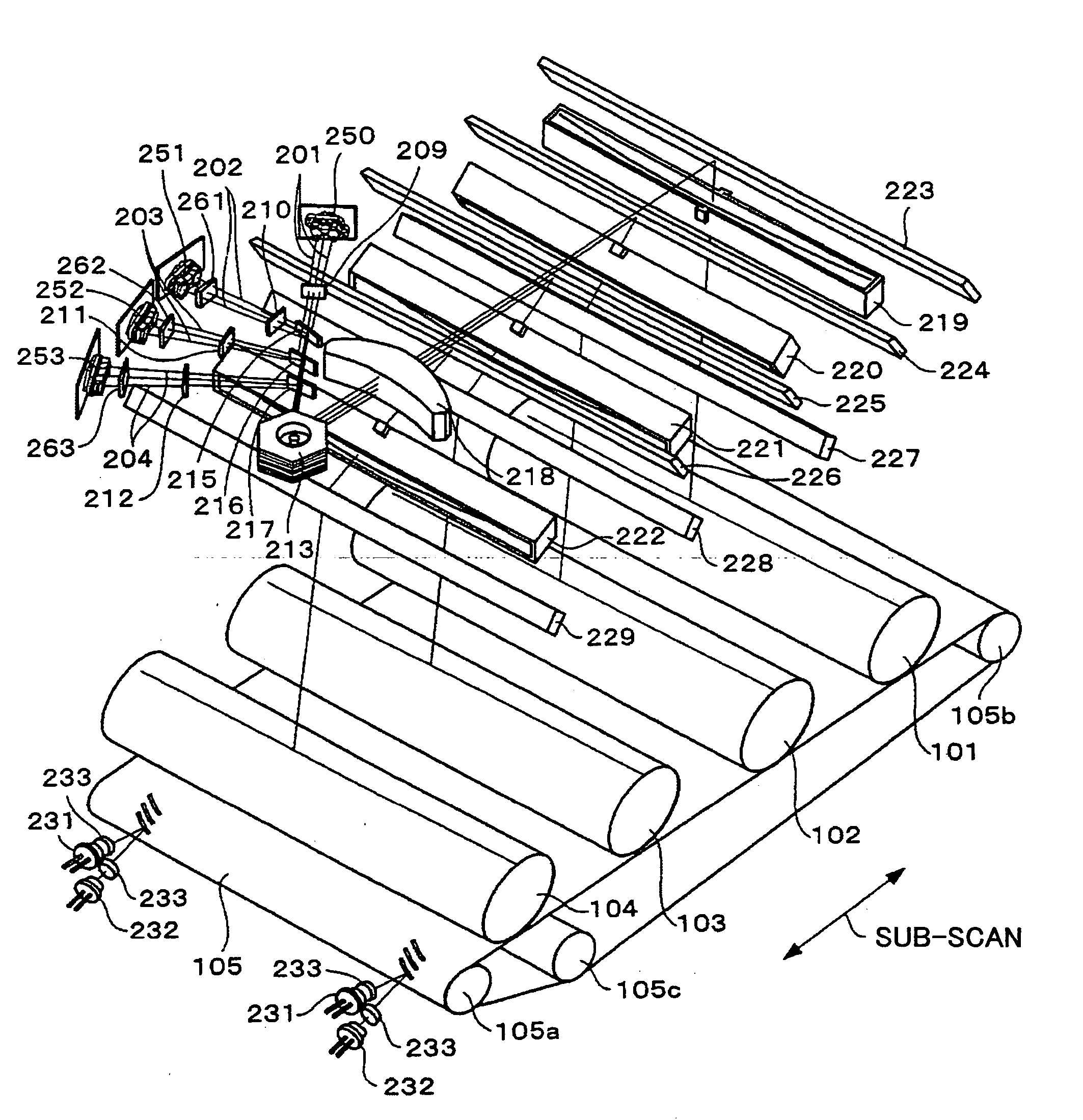
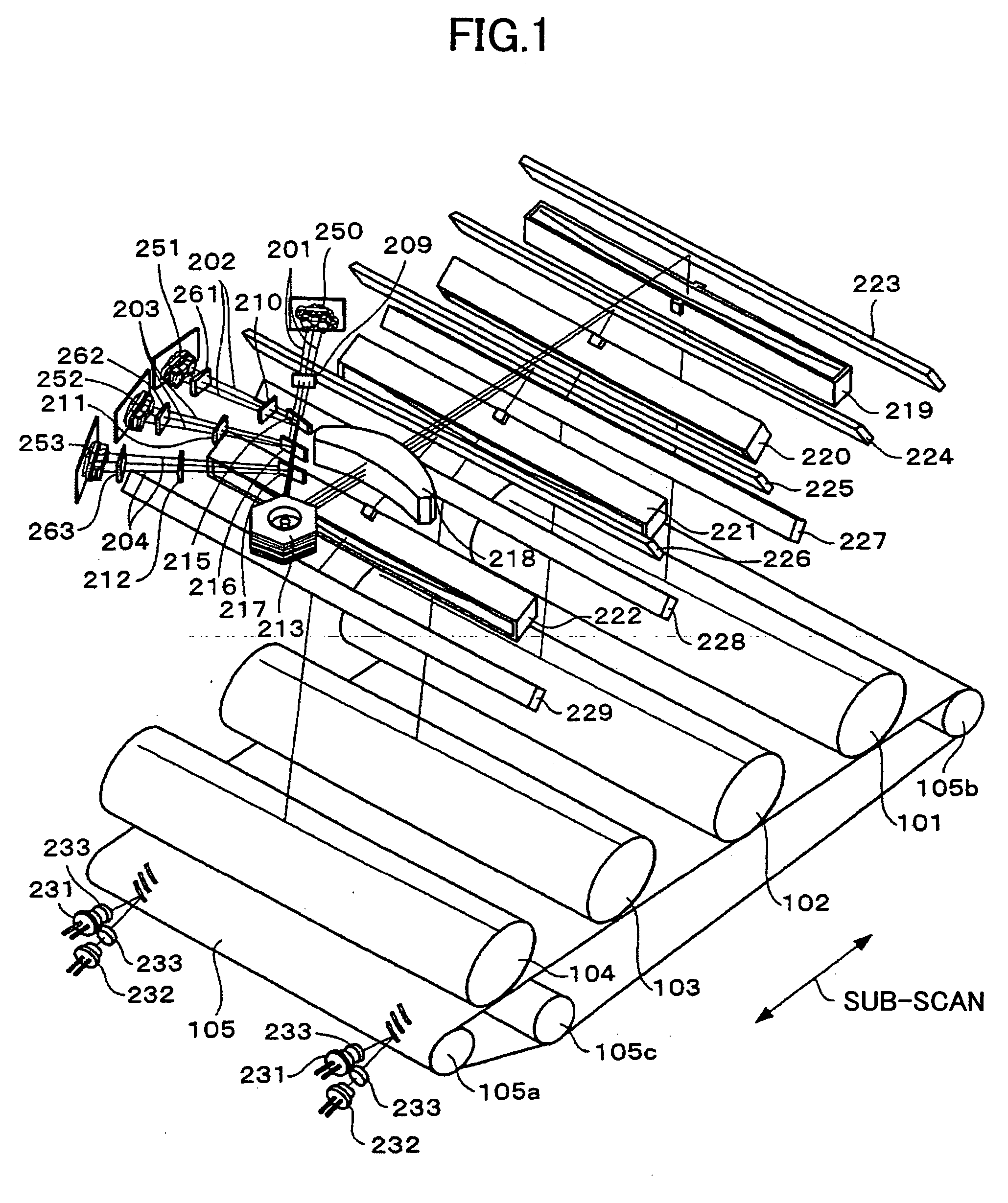
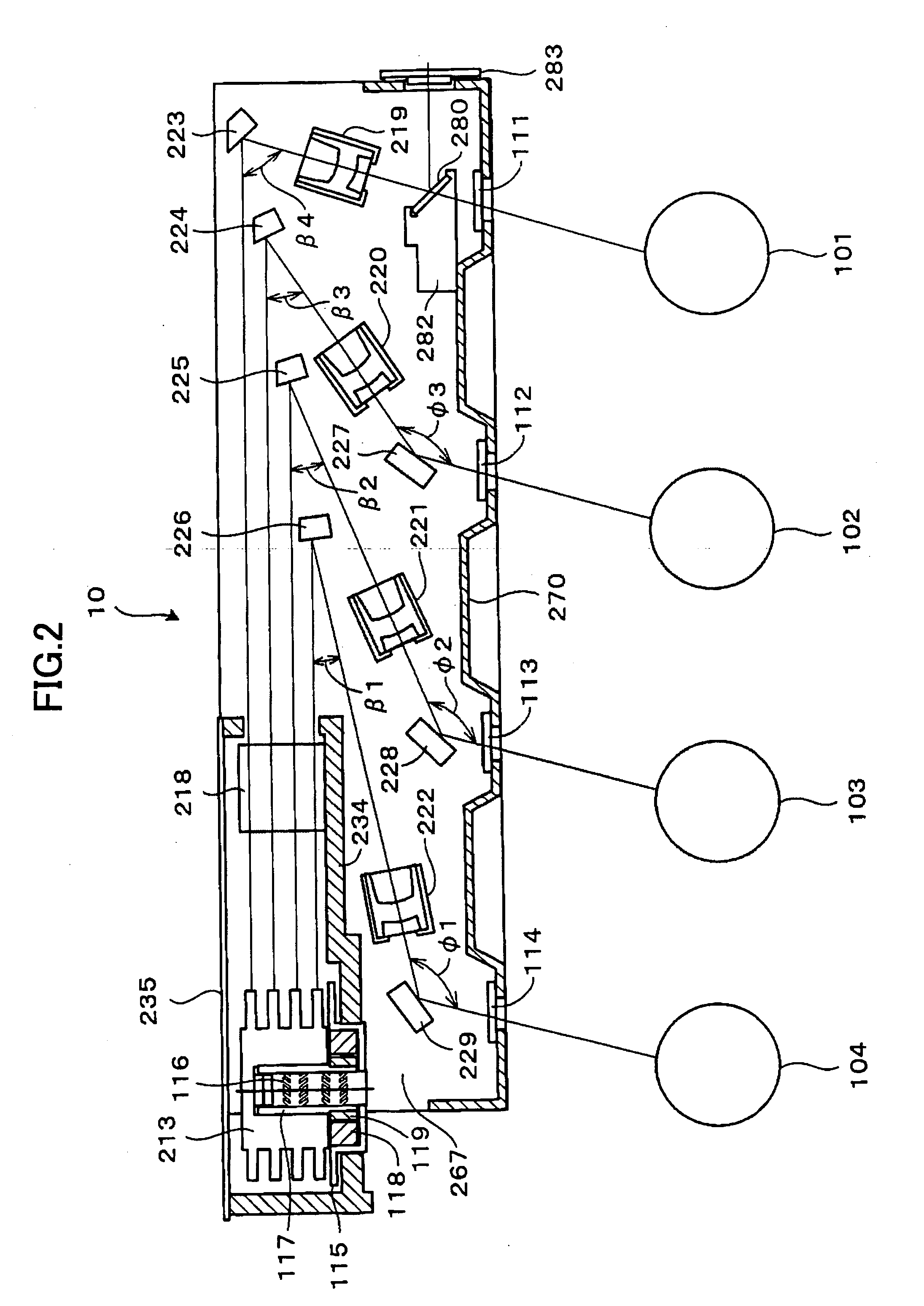
In one mode of the present invention, there is provided an optical scanning apparatus usable for an image forming apparatus of the tandem construction having plural image forming stations for formation of respective different color images and providing high positional precision for the scanning lines in each of the foregoing image forming stations, by using a low cost but rigid metal plate for the side plate members used for supporting the deflection mirrors such that the optical beams are directed to the respective photosensitive drums constituting the image carrier by way of such deflection mirrors. As a result of such a construction, the problem of unwanted size increase of the housing of the optical scanning apparatus with the use thereof in the image forming apparatus having plural image forming stations, is successfully eliminated.

Further, with the construction that gathers together those components of the respective image forming stations used with the optical beam before ...


PUM


Abstract

An optical scanning apparatus includes an optical source, a deflection part deflecting an optical beam emitted from the optical source, plural optical elements directing or focusing the optical beam deflected by the deflection part to corresponding one of plural image carrying bodies, a holding member holding the plural optical elements, wherein the optical beam scans the respective image carrying bodies in a main scanning direction, and wherein the holding member includes a pair of holding member elements disposed so as to face each other in the main scanning direction, and the plural optical elements are held between the pair of holding member elements in a bridged state.

Description

BACKGROUND OF THE INVENTION The present invention relates to an optical scanning apparatus used in an image forming apparatus such as a copying machine, facsimile, printer, and the like, and also to an image forming apparatus having such an optical scanning apparatus. Particularly, the present invention relates to an optical scanning apparatus and an image forming apparatus used for forming a color image by superimposing toner images of plural colors. In an image forming apparatus that uses a Carlson process, electrostatic latent images are formed on a rotating photosensitive drum used as an image carrier, and development and transfer of the electrostatic latent images are carried out subsequently. In order to carry out such formation of the electrostatic latent images, the image forming apparatus is equipped with an optical scanning apparatus that irradiates an optical beam on the surface of the photosensitive drum in the form of a laser beam according to the image information to...

Claims


Application Information

Patent Timeline
IPC IPC(8): B41J2/47G03G15/01
CPCG03G2215/0158G03G15/011
Inventor NAKAJIMA, TOMOHIRO
Owner RICOH KK
Why Eureka
Try Eureka