Method and apparatus for eliminating motion artifacts from video

a technology of motion artifacts and video, applied in the field of video compensation, can solve the problems of analog system, viewer's inability to discern blanked lines, faster display rate, etc., and achieve the effect of enhancing or improving the quality of video images

Inactive Publication Date: 2005-03-24
RGB SYST INC
View PDF44 Cites 21 Cited by
  • Summary
  • Abstract
  • Description
  • Claims
  • Application Information

AI Technical Summary

Benefits of technology

[0025] The invention defines a method and apparatus for detecting and correcting motion artifacts in interlaced video signal converted for progressive video display. An embodiment of the invention provides a method and apparatus for enhancing or improving the quality of video images by correcting the effects caused by converting the video signal from one type to another. For instance, an embodiment of the invention entails determining whether interlaced video material originated from a film source, thereby having been converted to video using a process known as 3-2 pulldown, and then correcting the interlaced video material to counteract the effect of the 3-2 pulldown. If the video material is concluded to originate from video because of inadequate confirmation of the 3-2 pulldown phenomenon, a check is made for the presence of “pixel motion” so that other necessary corrections may be applied. After appropriate corrections are applied, the resulting de-interlaced video material may be additionally processed using processes such as video scaling to generate a desired output resolution.

Problems solved by technology

However, because the display rate is faster than can be perceived by the human eye, a viewer is not able to discern the blanked lines.
One problem with NTSC is that it is an analog system.
However, if the NTSC data originating from film source is subsequently converted to progressive video for display on a computer display, for example, a problem known as “field motion” may occur.
Although the concept seems simple, scan converters use complex technology to achieve signal conversion because computer signals and television signals differ significantly.
For instance, current systems lack an effective way to eliminate field motion from interlaced video material during the conversion to progressive video.

Method used


Image

  • Method and apparatus for eliminating motion artifacts from video
  • Method and apparatus for eliminating motion artifacts from video
  • Method and apparatus for eliminating motion artifacts from video

Examples


Embodiment Construction

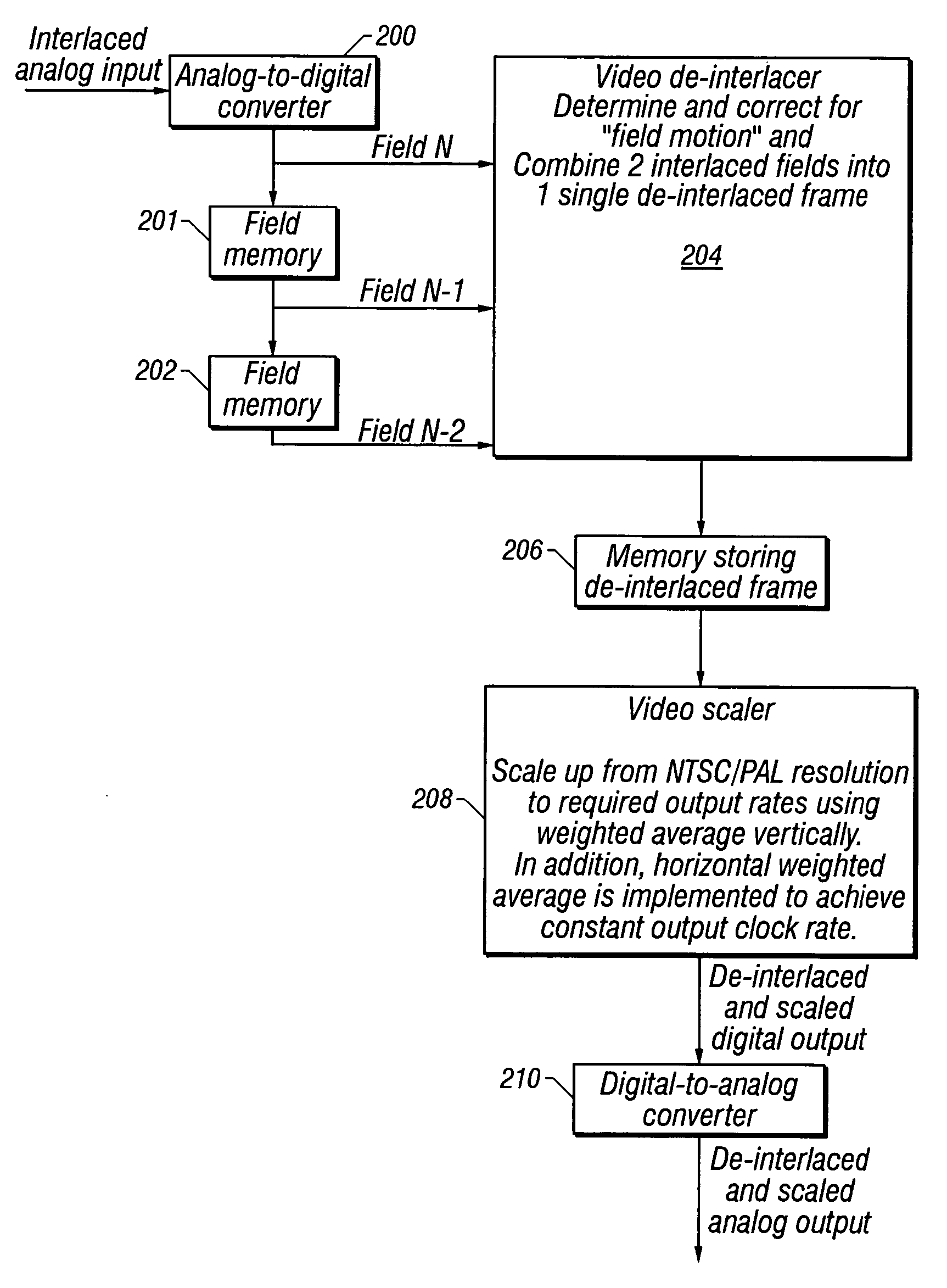
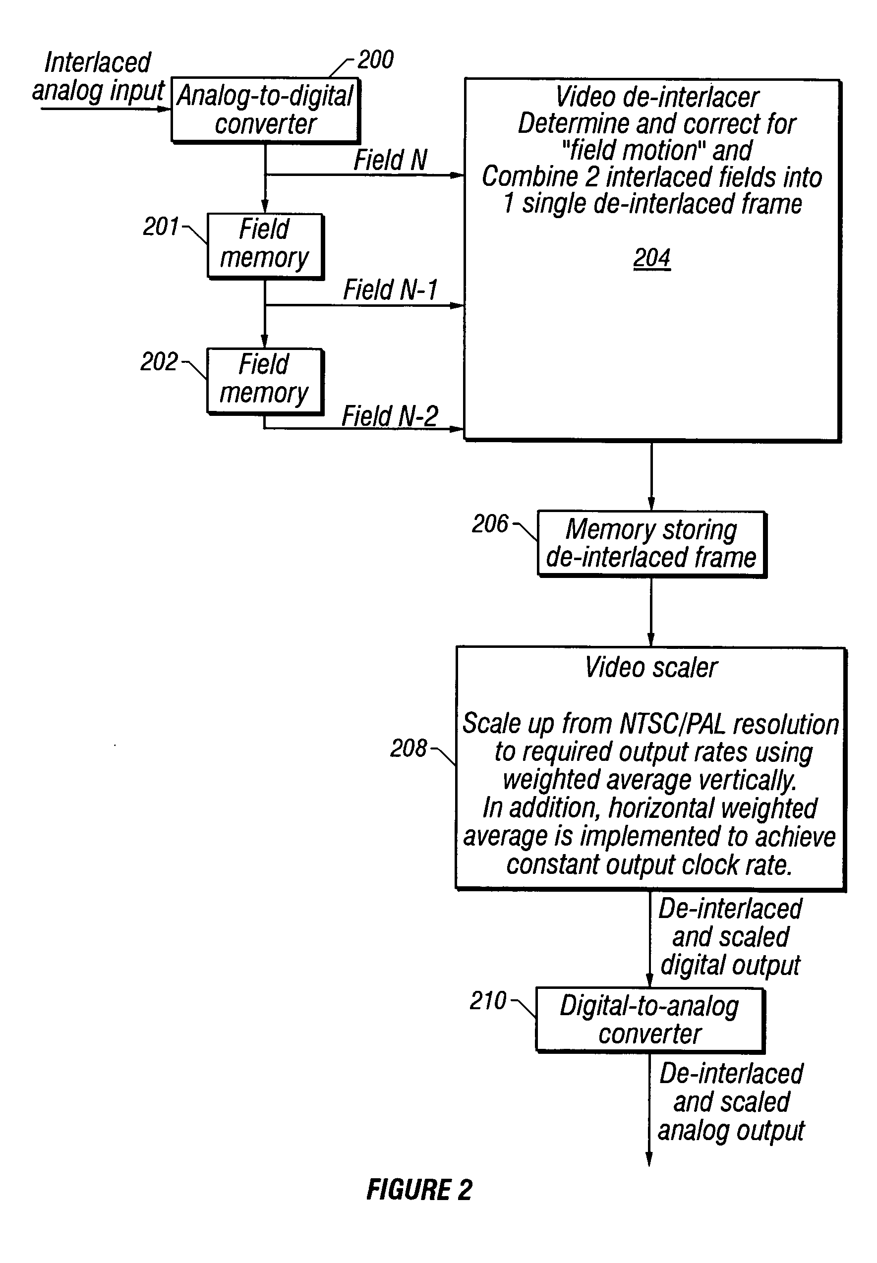
[0038] An embodiment of the invention comprises a method and apparatus for detecting and correcting motion artifacts in interlaced video signal converted for progressive video display. In the following description, numerous specific details are set forth to provide a more thorough description of embodiments of the invention. It will be apparent, however, to one skilled in the art, that the invention may be practiced without these specific details. In other instances, well known features have not been described in detail so as not to obscure the invention.

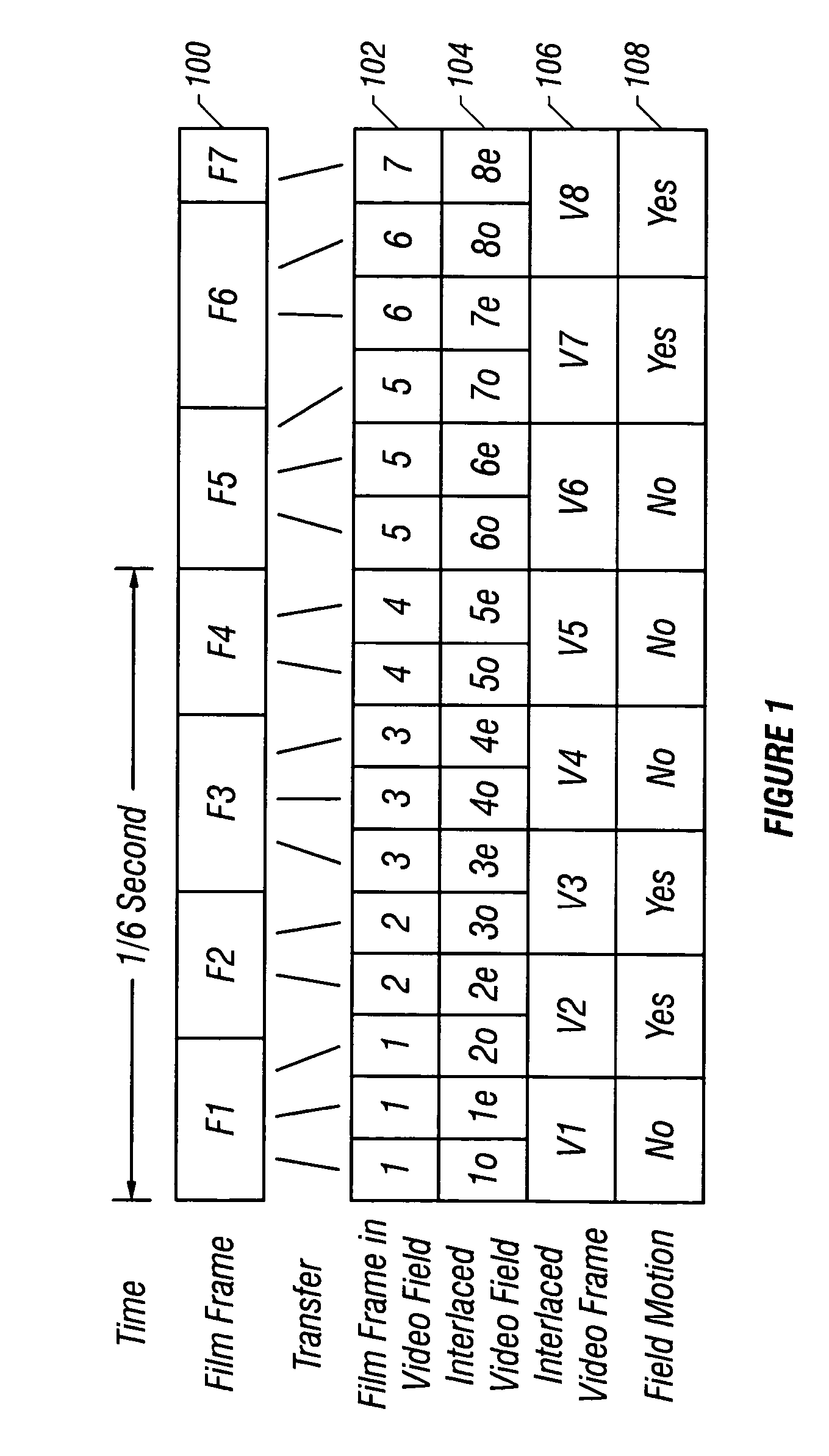
[0039] An embodiment of the invention provides a method and apparatus for enhancing or improving the quality of video images by correcting the effects caused by converting the video signal from one type to another. For instance, one embodiment of the invention eliminates field motion from interlaced video material during conversion to progressive video. An embodiment of the present invention entails determining whether the interlac...


PUM


Abstract

A method and apparatus for detecting and correcting motion artifacts in interlaced video signal converted for progressive video display. A correction is applied where interlaced video material is determined to originate from film source, thereby having been converted to video using a process known as 3-2 pulldown. Where the video material is not a result of the 3-2 pulldown process, a check is made for the presence of “pixel motion” so that corrections may be applied to smooth out the pixel motion. To determine 3-2 pulldown or field motion, a video field is compared to the field prior to the previous field to generate field error. Field errors are generated for five consecutive fields and a local minimum error repeated every five fields indicate the origination of the video material from film source using the 3-2 pulldown process. Upon confirmation of 3-2 pulldown, the video material is modified to correct for the mixing of two film frames into one interlaced video frame by assuring that the two fields of the de-interlaced video frame contain data from the same film frame. Where the video material did not originate from a film source, but pixel motion is detected, the pixel motion is smoothed out by an averaging method. The odd and even fields of the resulting video data are subsequently combined to form a progressive video material.

Description

BACKGROUND OF THE INVENTION [0001] 1. Field of the Invention [0002] This invention relates to the field of video compensation. More specifically the invention relates to detecting and correcting motion artifacts in video source signals. [0003] 2. Background Art [0004] In North America the video displayed across a normal television screen is an interlaced video signal, which is a standard called NTSC (National Television Standards Committee) video. This is not the same video displayed across most computer screens since computer screens use mostly non-interlaced display devices. [0005] Interlaced video simply means that for each picture frame displayed on the television screen, there are two video fields being displayed one after the other. The first field is commonly known as the odd field, and the second field as the even field. Since the interlaced video frame is displayed at 30 frames (i.e. 60 fields) every second, the odd field is displayed in the first one sixtieth ({fraction (1...

Claims


Application Information

Patent Timeline
Patent Type & Authority Applications(United States)
IPC IPC(8): H04N7/01
CPCH04N7/012H04N7/0112
Inventor TANG, CHE WINGTRUONG, DUNG DUC
Owner RGB SYST INC
Why Eureka
Try Eureka