
Thermometer having a disposable temperature probe

Inactive Publication Date: 2005-03-24
YU CHU YIH
View PDF26 Cites 1 Cited by
  • Summary
  • Abstract
  • Description
  • Claims
  • Application Information

AI Technical Summary

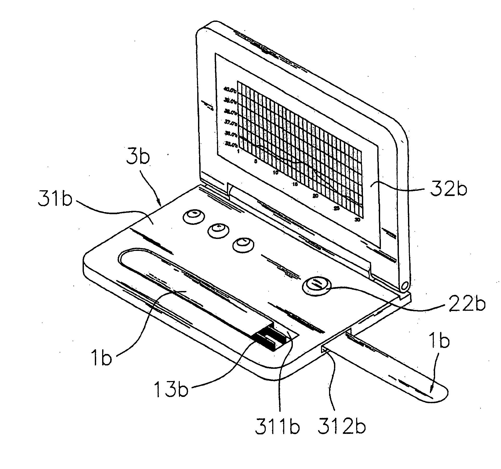
Benefits of technology

[0010] With the disposable temperature probe, the sanitary issue is greatly improved and the thermometer of the invention is thus applicable to different people. According to one aspect of the invention, the thermometer is comprised of a disposable temperature probe and a temperature recorder. The disposable temperature probe is a flat or tubular shape, and offers a fast time response. Its thermal sensor is designed to reach an equilibrium temperature immediately, which leads to reduction of time response up to 50% by experiments. The thermometer of the invention can effectively shorten the measurement time without the use of a heater, therefore, the circuit complexity is simplified and the production cost is reduced.
[0011] The temperature recorder includes a slot for the installation of the disposable temperature probe, and secures the disposable temperature probe by a latch. When performing measurement, the latch causes the disposable temperature probe not to fall off or prevents it from being eaten accidentally. To approach the equilibrium temperature instantly, the entire wires, or at least a portion of each wire, within a hollow cavity, are preferably bonded to the inside of a thermal contact surface. In close contact with flesh in a body cavity, the thermal contact surface serves as a heater such that the wires come to the equilibrium temperature rapidly. Thus, the measurement time is dramatically reduced. Note that the wires are bonded using an insulating material with good thermal conductivity. Preferably, the wires, within the hollow cavity, are bonded to the inside of the thermal contact surface with epoxy resin.

Problems solved by technology

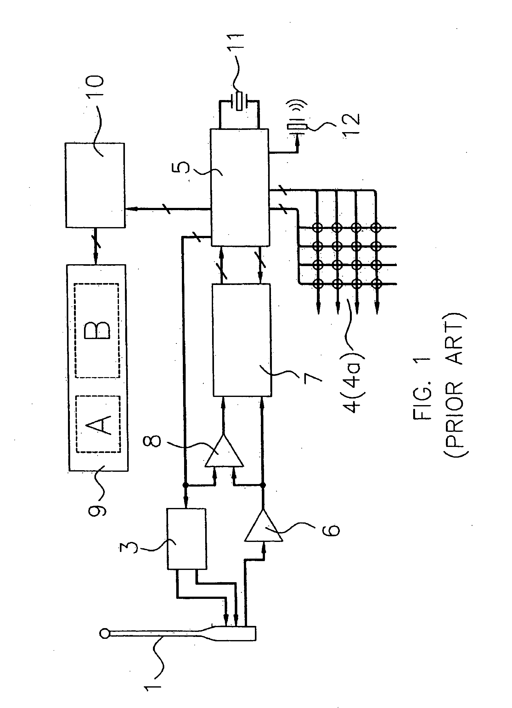
However, the prior art instrument has some drawbacks such as high circuit complexity, high energy consumption and high production cost due to its built-in heating circuit 3.
Hence, the prior art is not applicable to different people for the sanitary issue.

Method used


Image

  • Thermometer having a disposable temperature probe
  • Thermometer having a disposable temperature probe
  • Thermometer having a disposable temperature probe

Examples


Embodiment Construction

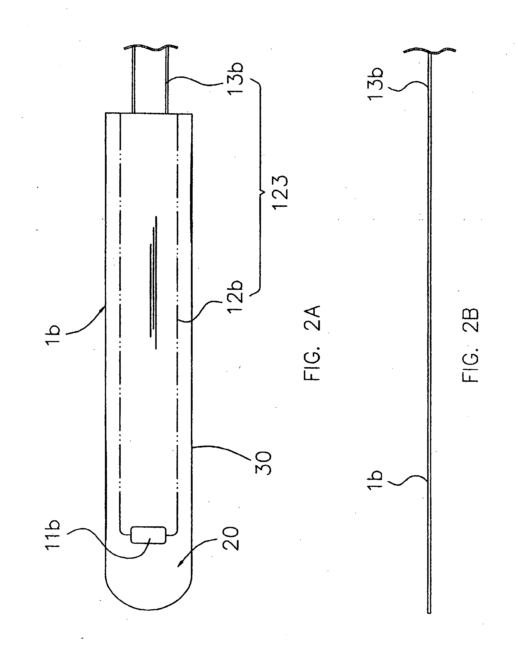
[0021] One embodiment of a disposable temperature probe is illustrated in FIGS. 2A and 2B. The flat disposable temperature probe (or test strip) 1b includes a hollow tip member 20 having a thermal contact surface 30. A thermal sensor 11b is mounted on the inside of the thermal contact surface 30. It senses the temperature of the thermal contact surface 30 and generates a temperature signal. A transmission means 123 is connected to the thermal sensor 11b to transmit the temperature signal. At least a portion of the transmission means 123 is preferably bonded to the inside of the thermal contact surface 30. The transmission means 123 is comprised of a set of wires 12b and a connector 13b. The wires 12b are arranged in the hollow tip member 20. To reduce the measurement time, a portion of the wires 12b is bonded to the inside of a thermal contact surface 30 in accordance with the invention. The connector 13b is electrically coupled to the set of wires 12b and extended out of the dispos...


PUM


Abstract

According to one aspect of the present invention, a thermometer with a disposable temperature probe is disclosed. The disposable temperature probe is made up of a hollow tip member, a thermal sensor and a transmission means. The hollow tip member has a thermal contact surface surrounding a hollow cavity and the thermal sensor is mounted on the inside of the contact surface. The thermal sensor senses the temperature of the thermal contact surface and generates a temperature signal. The transmission means is used to transmit the temperature signal. The thermometer also includes a temperature recorder having a slot for the installation of the disposable temperature probe. The temperature recorder is provided with a latch to fasten the disposable temperature probe.

Description

CROSS-REFERENCE TO RELATED APPLICATION [0001] The present application is a continuation-in-part of U.S. patent application having Ser. No. 10 / 413,163 filed on Apr. 14, 2003, which is a continuation-in-part of U.S. patent application having Ser. No. 10 / 050,122 filed on Jan. 18, 2003, the disclosures of which are hereby incorporated by reference herein. [0002] The present application is also a continuation-in-part of U.S. patent application having Ser. No. 10 / 274,220 filed on Oct. 18, 2002, which is hereby incorporated by reference in its entirety.BACKGROUND OF THE INVENTION [0003] 1. Field of the Invention [0004] The invention relates to the field of thermometers. More particularly, the invention relates to a disposable thermometer probe works in conjunction with a temperature record for measurement of a patient's temperature, although it is equally applicable to other temperature measurement fields. [0005] 2. Description of the Related Art [0006] U.S. Pat. No. 4,488,560, issued Dec....

Claims


Application Information

Patent Timeline
IPC IPC(8): G01K1/08G01K1/18G01K13/00
CPCG01K1/083G01K13/002G01K1/18G01K13/25G01K13/20
Inventor YU, CHU-YIH
Owner YU CHU YIH
Learn More