Focal plane shutter for digital still cameras

a shutter and digital still technology, applied in the field of optical plane shutters for digital still cameras, can solve the problems of troublesome operation, large motive power and rotors, and not necessarily favorable, and achieve the effects of reducing size and cost, simplifying the transmission structure of the drive member of the shutter blade, and reducing the size and cost of shutters

Inactive Publication Date: 2005-03-24
COPAL CO LTD
View PDF8 Cites 40 Cited by
  • Summary
  • Abstract
  • Description
  • Claims
  • Application Information

AI Technical Summary

Benefits of technology

[0012] In a focal plane shutter for digital still cameras having one shutter blade according to the present invention, a general-purpose inexpensive DC motor completed as a motor unit in advance is used for a drive source for driving the shutter blade. Moreover, a transmission structure to the drive member of the shutter blade is simplified so that the shutter assemble process is efficient and the shutter can be significantly reduced in size and cost.

Problems solved by technology

However, in view of manufacturing, it is not necessarily favorable.
Hence, the rotor requires large motive power and must withstand such large impact.
If a drive device fails in the inspection, the motor components must be disassembled and then reassembled, resulting in very troublesome operation and high cost.
However, when such a general-purpose motor is used, since a transmission mechanism to the drive member is complicated, the entire drive device becomes large in size, and although the motor itself is inexpensive, the entire cost is pushed up.

Method used


Image

  • Focal plane shutter for digital still cameras
  • Focal plane shutter for digital still cameras
  • Focal plane shutter for digital still cameras

Examples


first embodiment

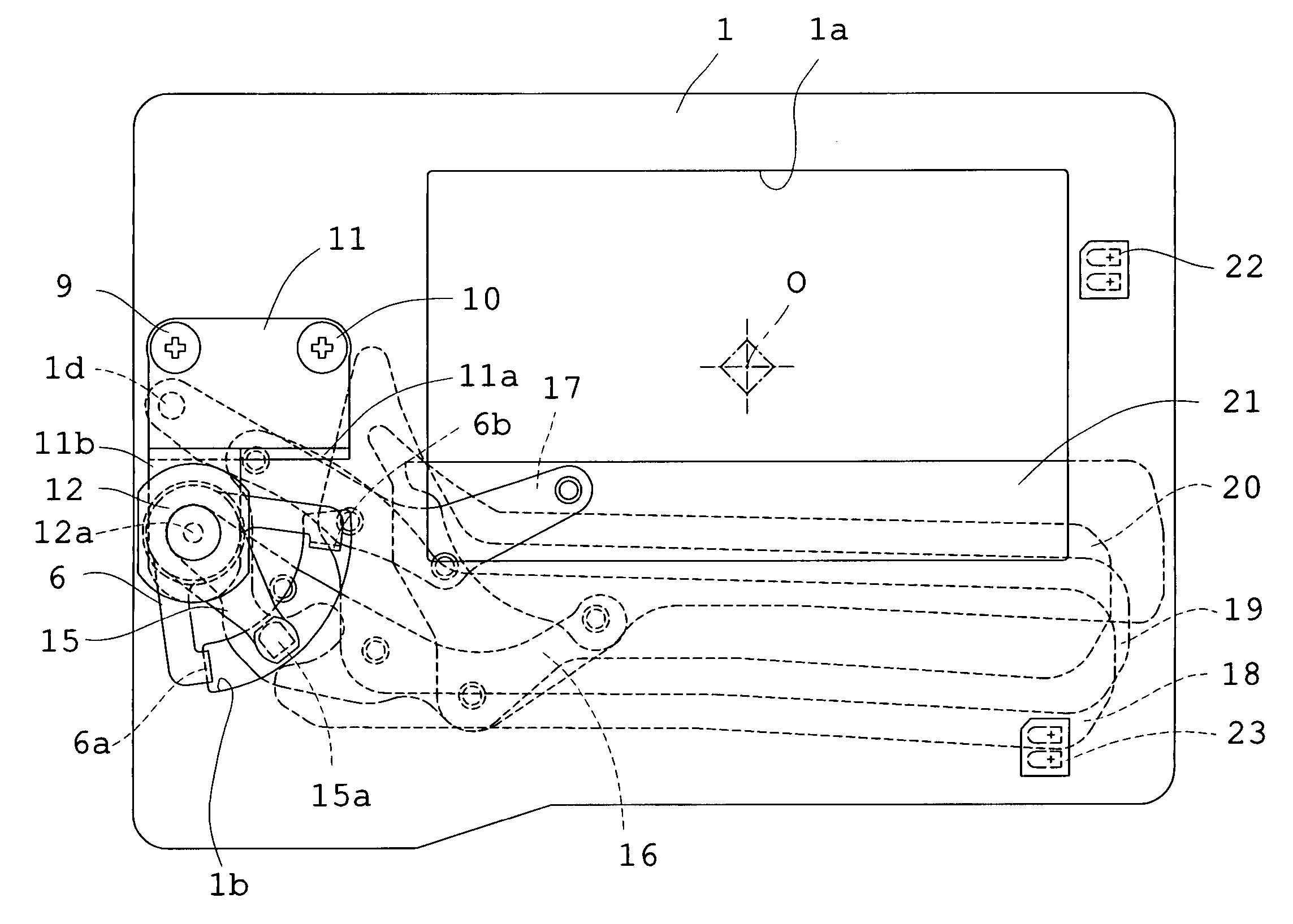
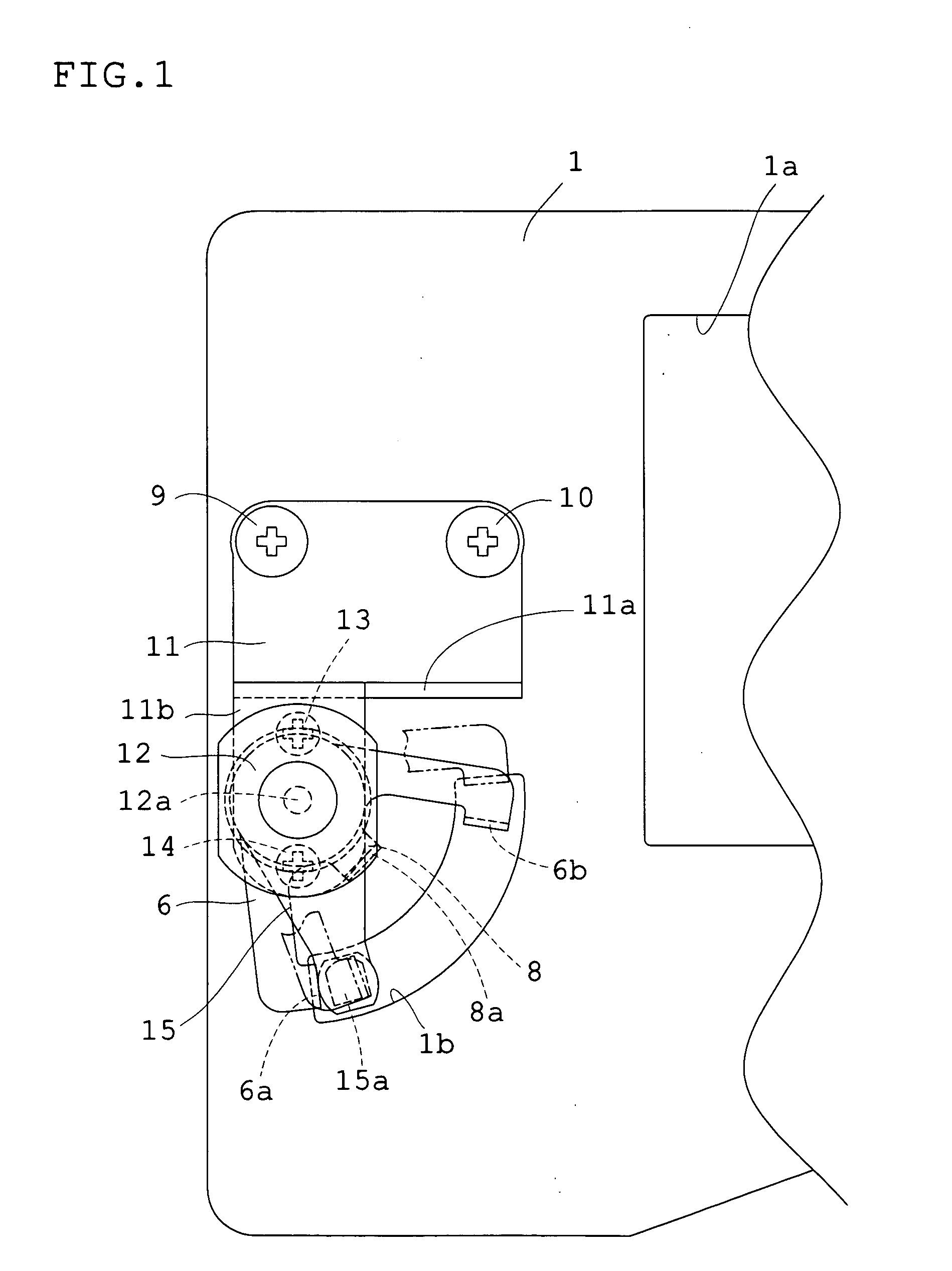
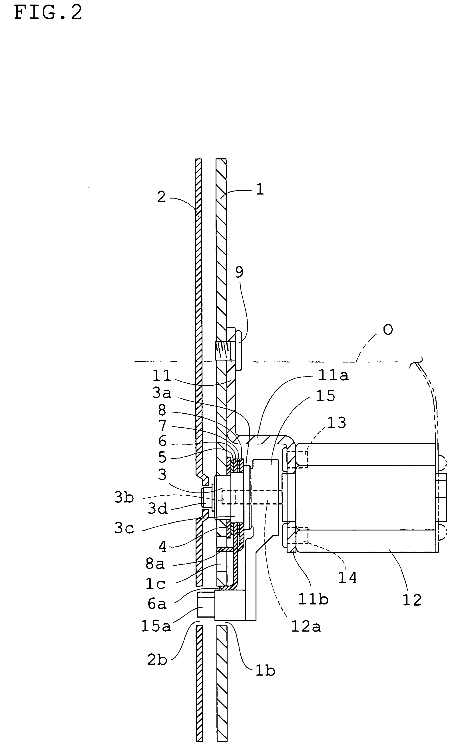
[0041] First, the first embodiment will be described with reference to FIGS. 1 to 7. FIG. 1 is a plan view for illustrating a drive device according to the first embodiment; FIG. 2 is a longitudinal sectional view of FIG. 1; and FIGS. 3 to 7 are for illustrating the operation according to the first embodiment. That is, FIG. 3 is a plan view showing an initial state of a shutter blade, in which an exposure opening is fully opened; FIG. 4 is a plan view showing a state of the shutter blade, in which the exposure opening is just started closing; FIG. 5 is a plan view showing a state of the shutter blade, in which the exposure opening is just before finished closing; FIG. 6 is a plan view showing a stopped state of the shutter blade just after finishing closing the exposure opening; and FIG. 7 is a timing chart for illustrating a series of the operations.

[0042] First, the structure of a drive device according to the embodiment will be described. A shutter base board 1 is provided with ...

second embodiment

[0057] Next, a second embodiment will be described. FIG. 8 is a plan view showing a substantially half-closed state of the exposure opening of a shutter blade according to the second embodiment after starting the closing operation from the initial state shown in FIG. 3 in the same way as in the shutter blade according to the first embodiment; FIG. 9 is a timing chart for illustrating the operation according to the embodiment. Whereas the shutter according to the first embodiment has the two optical sensors 22 and 23, the shutter according to the second embodiment includes one optical sensor 24 as shown in FIG. 8. Other structures of this embodiment are the same as those of the first embodiment, so that in FIG. 8, like reference numerals designate like components common to each embodiment.

[0058] The optical sensor 24 according to the embodiment is a photo-reflector with the same structure as in the optical sensors 22 and 23 according to the first embodiment. The optical sensor 24, a...

third embodiment

[0065] A third embodiment will be described with reference to FIGS. 10 to 15. FIG. 10 is a plan view for illustrating the structure of a drive device according to the third embodiment; FIG. 11 is a longitudinal sectional view of FIG. 10; and FIGS. 12 to 15 are drawings for illustrating the operation according to the embodiment, wherein FIG. 12 is a plan view showing an initial state of a fully-opened exposure opening, FIG. 13 is a plan view showing a state of the exposure opening immediately after a shutter blade starts closing it, FIG. 14 is a plan view showing a state of the exposure opening immediately before the shutter blade finishes closing it, and FIG. 15 is a plan view showing a state of the exposure opening in which the shutter blade stops immediately after finishing to close it. FIG. 7 used for the first embodiment will be also used for illustrating the operation according to the third embodiment.

[0066] First, a structure according to the embodiment will be described. In ...


PUM


Abstract

A drive member attached to the output shaft of a DC motor placed on a shutter base board includes a drive pin connected to the arm of a shutter blade within a blade chamber for driving the shutter blade to open and close an exposure opening with the reciprocal rotation of the DC motor. A brake member rotatably attached to the shutter base board and having a frictional force applied thereto by a spring washer brakes the rotation of the drive member when a bent portion is pushed by the drive pin to rotate.

Description

BACKGROUND OF THE INVENTION [0001] 1. Field of the Invention [0002] The present invention relates to a focal plane shutter for digital still cameras having one shutter blade. [0003] 2. Description of the Related Art [0004] Among focal plane shutters for digital still cameras, there is a shutter including only one shutter blade composed of a plurality of arms, each with one end pivoted on a base board, and at least one blade pivoted on these arms. The shutter blade opens / closes an opening of an imaging optical path by the reciprocating rotation of a drive member which is connected to one of the arms via a drive pin. It has been known that the drive member uses a set member linked to a motor for rotation in one direction while using an urging force of a spring in the other direction. The reciprocating rotation only by a motor has become of interest lately. Then, as a device advanced further than this, a drive device in that a drive member is integrated with a motor rotor is disclosed ...

Claims


Application Information

Patent Timeline
Patent Type & Authority Applications(United States)
IPC IPC(8): G03B9/40
CPCG03B9/40
Inventor USUDA, YUICHIROUTAKAHASHI, SHIGEMI
Owner COPAL CO LTD
Why Eureka
Try Eureka