Heat dissipation fan

a technology of heat dissipation fan and fan blade, which is applied in the direction of machines/engines, stators, liquid fuel engines, etc., can solve the problems of reducing the operation efficiency of the fan, forming gaps, and damage to the fan blades, so as to eliminate the distance between the fan blade and the casing bottom, the effect of eliminating the damage caused by undesired impact and reducing the turbulen

Inactive Publication Date: 2005-03-24
AVERATEC ASIA +2
View PDF2 Cites 5 Cited by
  • Summary
  • Abstract
  • Description
  • Claims
  • Application Information

AI Technical Summary

Benefits of technology

[0006] An object of the present invention is to provide a heat dissipation fan wherein a stuffing pad is disposed on a bottom of a casing housing a rotary fan assembly in order to substantially eliminating the distance between fan blades and the casing bottom.
[0007] Another object of the present invention is to provide a heat dissipation fan wherein a soft pad is arranged between a fan assembly and a casing to eliminate damage caused by undesired impact of the fan with the casing.
[0008] A further object of the present invention is to provide a heat dissipation fan wherein a gap between fan blades and a casing is effectively eliminated while the fan blades are maintained impact free with respect to the casing.
[0009] To achieve the above objects, in accordance with the present invention, there is provided a heat dissipation fan comprising a casing having a bottom wall and a side wall extending from the bottom wall and defining an open top of the casing. The side wall itself defines a side opening. A rotary fan assembly is housed in the casing and is rotatably supported on the bottom wall. The fan assembly comprises fan blades that are spaced from the bottom wall of the casing whereby a gap is formed therebetween. Air is drawn into the casing by the fan blades via the open top of the casing and driven out of the casing through the side opening. A stuffing pad is arranged in the gap and positioned on the bottom wall to reduce the gap wherein air flowing to the back side of the fan blades is limited and turbulence induced thereby is alleviated. The stuffing pad is made of a soft material whereby damage may not occur on the fan blades when the fan blades impact the stuffing pad.

Problems solved by technology

Since the fan blades are rotated at a high speed, undesired impact of the fan blades with the bottom of the casing inevitably causes damage to the fan blades.
However, a large gap is formed between the fan blades and the bottom of the casing, air that is sucked into the fan in an axial direction may flow to the back side of the fan blades, rather than being driven out of the fan along the side opening by centrifugal force.
The air that flows to the back side of the fan blades induces turbulence that interferes with the air flowing toward the side opening and thus reducing the operation efficiency of the fan.

Method used


Image

  • Heat dissipation fan
  • Heat dissipation fan
  • Heat dissipation fan

Examples


Embodiment Construction

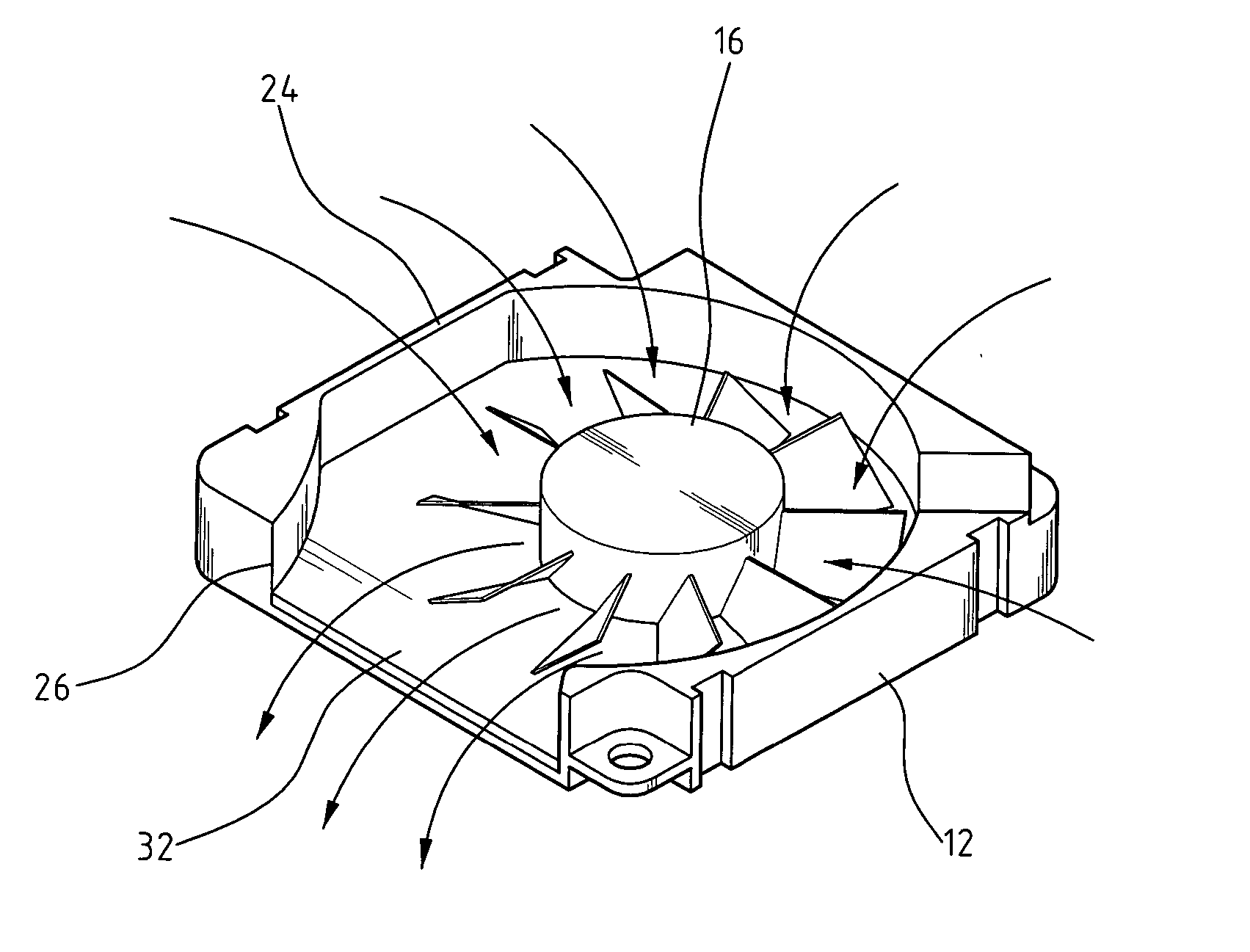
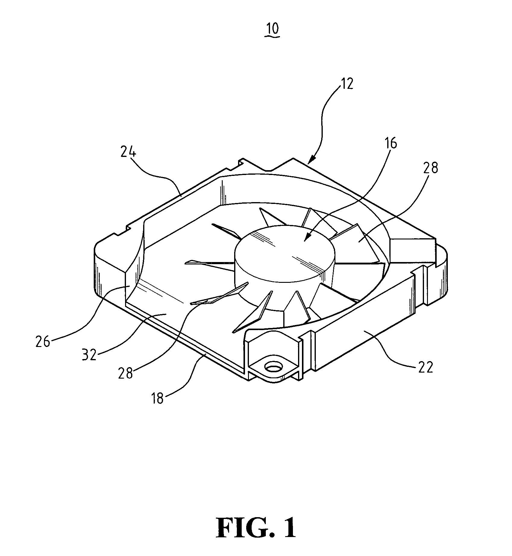
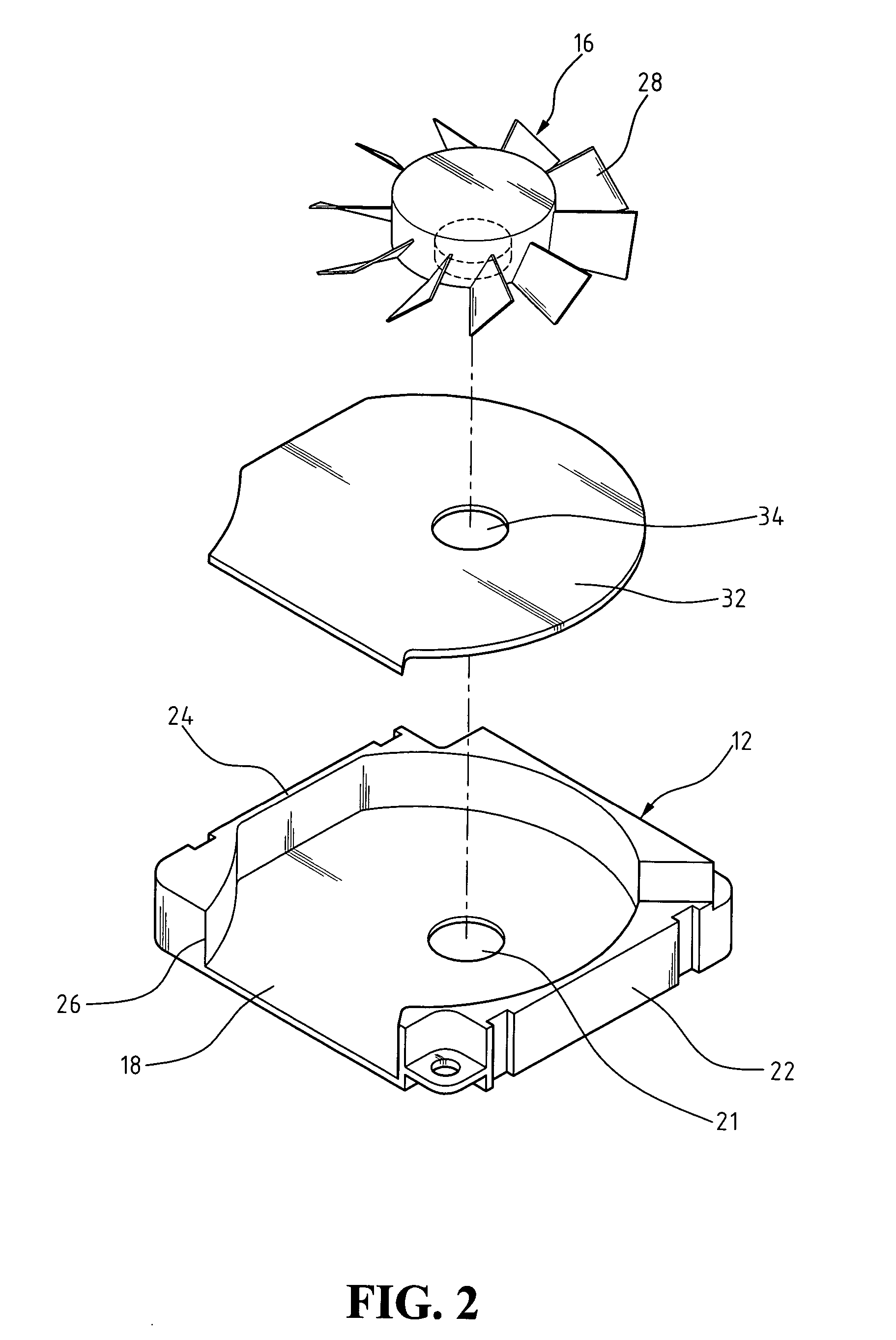
[0015] With reference to the drawings and in particular to FIG. 1, a heat dissipation fan constructed in accordance with the present invention, generally designated with reference numeral 10, comprises a casing 12 made of a rigid material, such as metal and hard plastics. The casing 12 defines a cavity 14 in which a fan assembly 16 is received. The casing 12 has a bottom wall 18 on which the fan assembly 16 is rotatably supported. For example, a shaft 20 of the fan assembly 16 extends through a bore 21 defined in the bottom wall 18 and supported by bearing means (not shown). Alternatively, the shaft 20 is fixed to and extends from the bottom wall 18 into the cavity 14 to which the fan assembly 16 is rotatably mounted. The casing 12 comprises a side wall 22 extends from the bottom wall 18 to define an open top 24 of the casing 12. A side opening 26 in communication with the cavity 14 is defined in the side wall 22.

[0016] Also referring to FIGS. 2 and 3, the fan assembly 16 comprises...


PUM


Abstract

A heat dissipation fan includes a casing having a bottom wall and a side wall extending from the bottom wall and defining an open top of the casing. The side wall itself defines a side opening. A rotary fan assembly is housed in the casing and is rotatably supported on the bottom wall. The fan assembly includes fan blades that are spaced from the bottom wall of the casing whereby a gap is formed therebetween. Air is drawn into the casing by the fan blades via the open top of the casing and driven out of the casing through the side opening. A stuffing pad is arranged in the gap and positioned on the bottom wall to reduce the gap wherein air flowing to the back side of the fan blades is limited and turbulence induced thereby is alleviated. The stuffing pad is made of a soft material whereby damage may not occur on the fan blades when the fan blades impact the stuffing pad.

Description

BACKGROUND OF THE INVENTION [0001] 1. Field of the Invention [0002] The present invention relates generally to a heat dissipation fan, and in particular to a heat dissipation fan having reduced turbulence induced in the back side of fan blades and enhancing protection of the blades. [0003] 2. The Related Art [0004] Heat dissipation fans are commonly employed to enhance removal of heat generated in computers in order to maintain proper operation of the computers. A side-mount heat dissipation fan comprises a casing having an open top for intake of surrounding air and a side opening in communication with a heat sink to conduct air flow toward and through the heat sink. The casing has a bottom that is closed for supporting the fan blades thereon. Since the fan blades are rotated at a high speed, undesired impact of the fan blades with the bottom of the casing inevitably causes damage to the fan blades. To reduce the risk of impact, the fan blades are arranged at a sufficient distance f...

Claims


Application Information

Patent Timeline
Patent Type & Authority Applications(United States)
IPC IPC(8): F04D29/16
CPCF04D29/162
Inventor PARK, HEE-KEUN
Owner AVERATEC ASIA
Why Eureka
Try Eureka