Mobile terminal

a mobile terminal and terminal technology, applied in the field of mobile terminals, can solve the problems of antennas not being optimally connected to the reception circuit, large image data, and inability to transmit and receive data, so as to achieve energy saving and reduce power consumption

Active Publication Date: 2005-03-24
MAXELL HLDG LTD
View PDF18 Cites 23 Cited by
  • Summary
  • Abstract
  • Description
  • Claims
  • Application Information

AI Technical Summary

Benefits of technology

[0019] By the above arrangements, energy saving can be achieved by turning off the power supply to the reception circuit for space diversity during voice communication in which a small amount of voice data is exchanged.
[0020] According to this invention, a GPS-compatible mobile terminal comprises a change-over unit for changing over connections between the main antenna and the external monitor terminal, and the tran

Problems solved by technology

The volume of image data is generally large, and therefore its transmission and reception takes time.
However, in the prior art, no consideration was given to the switch unit wh

Method used


Image

  • Mobile terminal
  • Mobile terminal
  • Mobile terminal

Examples


first embodiment

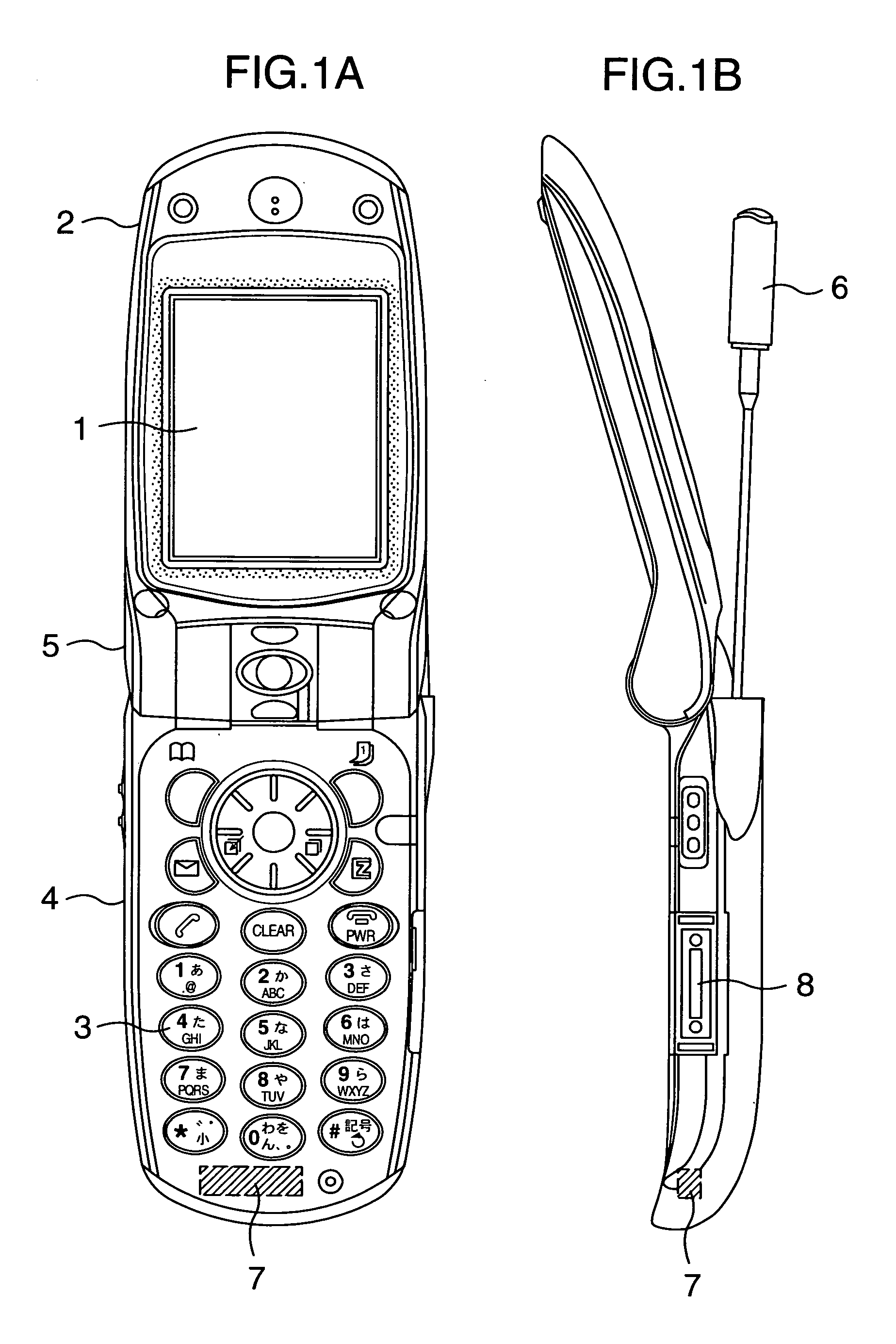
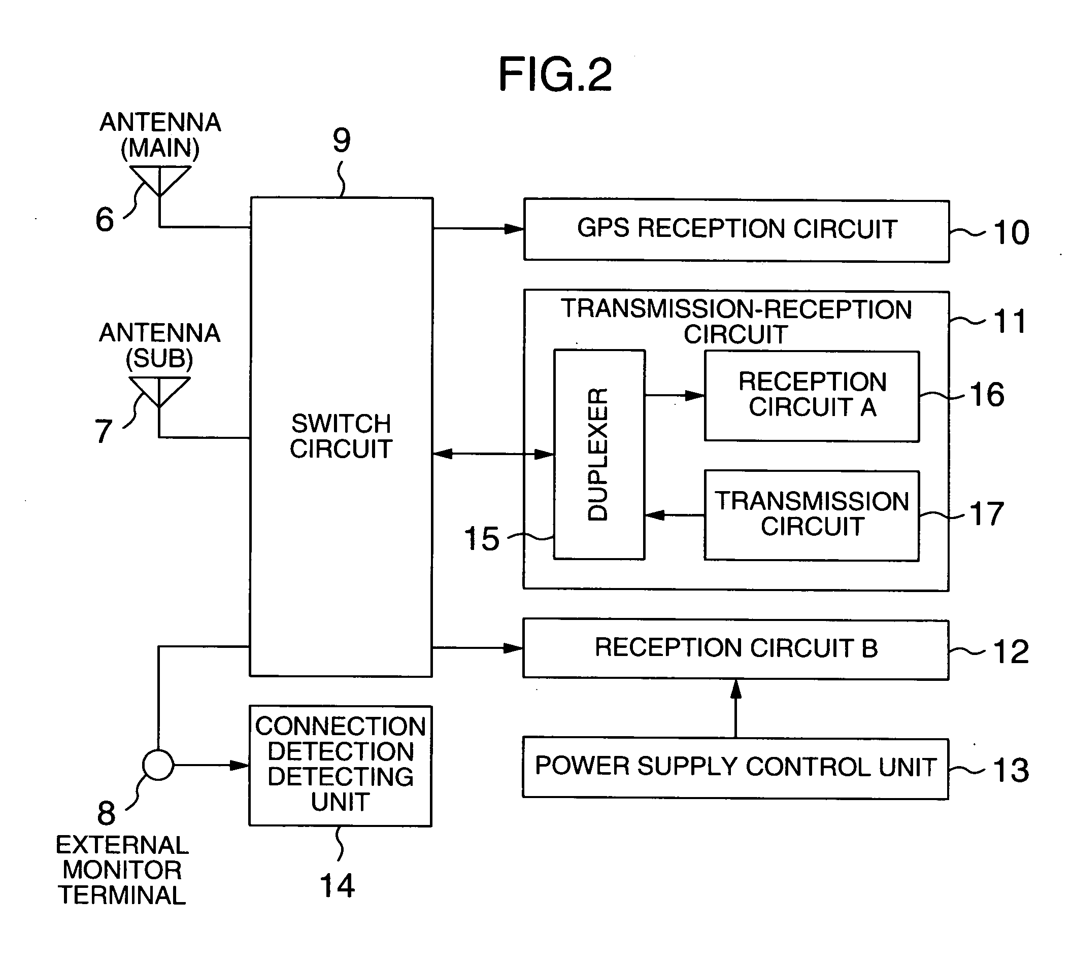
[0031] this invention will be described with reference to FIGS. 1 to 4. FIG. 1A is an external view drawing, viewed from the front, of a CDMA-system cell phone in the present invention (hereafter referred to as a cell phone). FIG. 1B shows an embodiment of the external appearance as viewed from the side, of the cell phone in this invention. A casing 2 with a display 1 formed by a liquid crystal panel and a casing 4 with operation buttons 3 can be opened and closed at a hinge 5. At the hinge 5 side of the casing 4, an antenna A 6 is retractably mounted as the main antenna to transmit and receive CDMA-system signals and to receive GPS signals. Inside the casing 4, an antenna B 7 is disposed as the sub antenna to receive CDMA-system signals and GPS signals. Moreover, at one side of the casing 4, an external monitor terminal 8 is provided to connect an outside antenna or to evaluate the transmission circuit and the reception circuits as the internal circuits. Normally, with the cell pho...

second embodiment

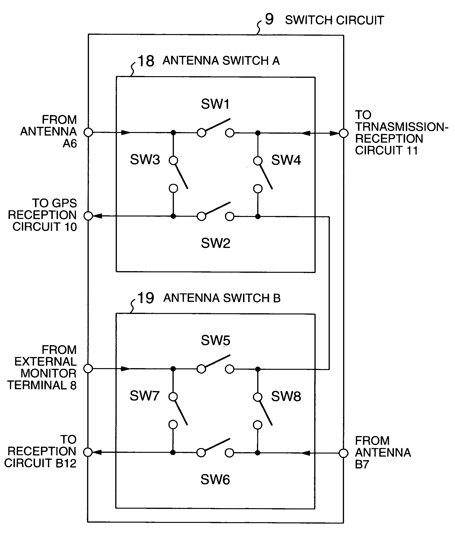
[0051] As described above, as the switch circuit 9 is formed in a circuit structure as shown in the second embodiment, only six pieces of change-over switches are required, which means that a reduction of space can be achieved, and the six kinds of operation modes can be realized by three kinds of switch on-off combinations, which means that the process load on the control unit can be decreased. The optimized layout of connections and the use of smaller number of switch on-off combinations as well as the size-reduced antenna B 7 contribute to the lessening of process load on the control unit. In short, this invention opens the way for reducing the size of the cell phones and their production cost.

[0052] Referring to FIG. 7, description will be made of power-saving control in the data communication mode according to a third embodiment of this invention. FIG. 7 is a flowchart showing the flow of process steps in power saving control in the data communication mode according to a third ...


PUM


Abstract

In a cell phone, no consideration is given to a switch unit when a reception circuit for space diversity is added, and consequently an antenna can be optimally connected to the reception circuit for space diversity. The cell phone comprises a first antenna for radio communication, a transmission-reception circuit to exchange signals with a base station through the first antenna, and a GPS reception circuit to receive signals from the GPS satellite through the first antenna. The reception circuit receives a signal from the base station, a second antenna different from the first antenna is provided, and the switch unit changes over connections between the first antenna and the second antenna, and the transmission-reception circuit, the GPS reception circuit and the reception circuit according to operation modes.

Description

INCORPORATION BY REFERENCE [0001] This application claims priority from Japanese application JP2003-327110 filed on Sep. 19, 2003, the content of which is hereby incorporated by reference into this application. BACKGROUND OF THE INVENTION [0002] 1. Field of the Invention [0003] This invention relates to a mobile terminal and more particularly to a technology for switching connections between an antenna unit and a transmission-reception circuit or respective receiving circuits. [0004] 2. Description of the Prior Art [0005] With the current cell phones, the connections between a transmission-reception circuit and a GSP reception circuit, and an antenna and an external monitor terminal are changed over by a switch unit. In the prior art of the switch unit, the switch unit is structured as follows. Four on-off switches are used in such a way that when signals are transmitted and received, the antenna unit is connected to the transmission-reception circuit, and when a GSP signal is recei...

Claims


Application Information

Patent Timeline
IPC IPC(8): H04B1/3822H04B1/40H04B1/44H04B7/08H04B7/26H04M1/00H04M1/02H04M1/21H04M1/725H04M1/73H04W16/28H04W52/02H04W88/02
CPCH04B1/3805H04B1/44H04W52/0274H04M2250/10H04B7/0814Y02D30/70
Inventor UOTSU, SHINICHIKUMEKAWA, MASANOBUCHIBA, YUTAKA
Owner MAXELL HLDG LTD
Why Eureka
Try Eureka