Beam assigning apparatus and method in a smart antenna system

a technology of smart antenna and forward beam, which is applied in the field of smart antenna devices, can solve the problems of limited radio resources, reverse radio capacity is usually smaller than the forward radio resource in the fdd cdma, and forward radio capacity is not increased

Inactive Publication Date: 2005-03-24
SAMSUNG ELECTRONICS CO LTD
View PDF5 Cites 12 Cited by
  • Summary
  • Abstract
  • Description
  • Claims
  • Application Information

AI Technical Summary

Benefits of technology

[0021] Another object of the present invention is to provide an apparatus and method for assigning a forward beam through an accurate analysis of the spatial spectrum of multipath propagation in a smart antenna system.

Problems solved by technology

The issue of efficient use of resources mainly concerns the utilization of limited radio resources.
The introduction of the smart antenna system arose from the challenge of confronting wireless subscriber growth, subscriber demands for increased data, and limited available radio resources.
However, the forward radio capacity is not increased simply by increasing the number of antennas in view of the radiation of the radio signal into a physical space.
Furthermore, the reverse radio capacity is usually smaller than the forward radio resource in the FDD CDMA system.
Learning to detect optimal forward beams for the multiple location grids is a very long process.
Furthermore, it may occur that optimal beams are different for location grids having the same AOA and TOA, which becomes a significant cause of decreased gain.

Method used


Image

  • Beam assigning apparatus and method in a smart antenna system
  • Beam assigning apparatus and method in a smart antenna system
  • Beam assigning apparatus and method in a smart antenna system

Examples


Embodiment Construction

[0042] An embodiment of the present invention will now be described herein below with reference to the accompanying drawings. In the following description, well-known functions or constructions are not described in detail since they would obscure the invention in unnecessary detail.

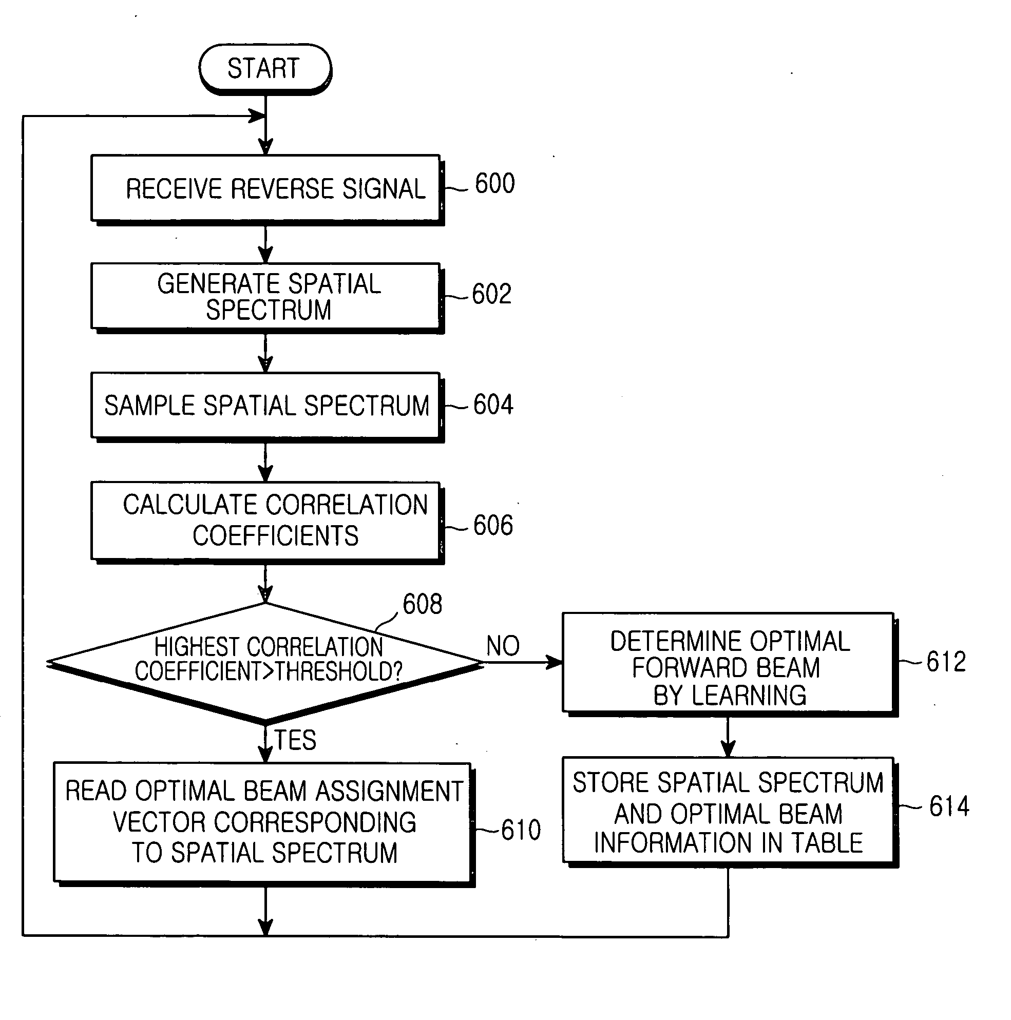
[0043]FIG. 3 is a diagram illustrating the operation of a smart antenna system according to an embodiment of the present invention. With reference to FIG. 3, the operation of the smart antenna system will be described below.

[0044] As described earlier, when a received reverse signal has the spatial spectrum 301 of FIG. 3, the conventional forward beam assignment 302 based on the peak energy only causes problems. Therefore, consideration must also be given to paths 310 and 311 in order to assign a beam more accurately. The resulting beam assignment is denoted by reference numeral 303 in FIG. 3. Yet, it should be appreciated that the beam assignment does not always occur in that manner in real implementat...


PUM


Abstract

A method and apparatus for assigning a forward beam using a received reverse signal in a smart antenna system are provided. A reverse signal is received from a wireless terminal, the spatial spectrum of the reverse signal is detected and sampled at a predetermined sampling rate, the correlation coefficients between the sampled spectral spectrum and spatial spectrum values stored in a spatial spectrum table are calculated, a forward beam assignment vector corresponding to the highest of the correlation coefficients is detected, and a forward beam is assigned using the forward beam assignment vector.

Description

PRIORITY [0001] This application claims the benefit under 35 U.S.C. § 119(a) to an application entitled “Beam Assigning Apparatus and Method in a Smart Antenna System” filed in the Korean Intellectual Property Office on Sep. 24, 2003 and assigned Serial No. 2003-66395, the entire contents of which are incorporated herein by reference. BACKGROUND OF THE INVENTION [0002] 1. Field of the Invention [0003] The present invention relates generally to a smart antenna device and a method thereof in a wireless communication system. In particular, the present invention relates to an apparatus and method for assigning forward beams in a wireless communication system using a smart antenna. [0004] 2. Description of the Related Art [0005] Wireless communication systems were introduced to enable users to communicate irrespective of location. While the first wireless communication systems focused on voice service, now mobile communication systems have been developed to transmit high-speed data and t...

Claims


Application Information

Patent Timeline
Patent Type & Authority Applications(United States)
IPC IPC(8): H01Q3/26H04B7/06
CPCH04B7/0619H04B7/0617
Inventor KIM, BYUNG-KI
Owner SAMSUNG ELECTRONICS CO LTD
Why Eureka
Try Eureka