

Internal saw for osteotomy of tubular bones
a tubular bone and sawing technology, applied in the field of internal saws for osteotomy of tubular bones, can solve the problems of difficult inserting and control, periosteum and surrounding tissue damage, and awkward operation
- Summary
- Abstract
- Description
- Claims
- Application Information
AI Technical Summary
Benefits of technology
Problems solved by technology
Method used
Image

Examples
Embodiment Construction
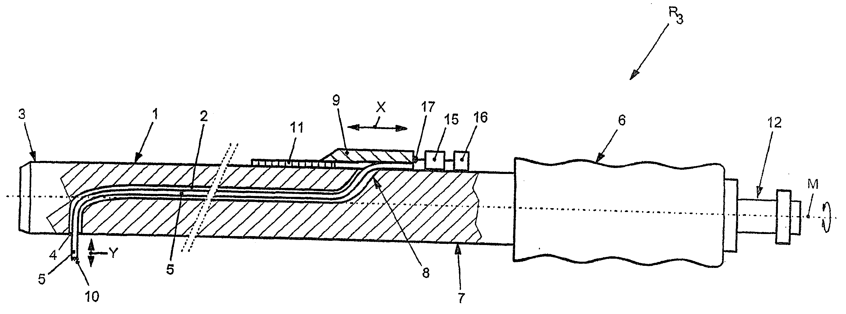
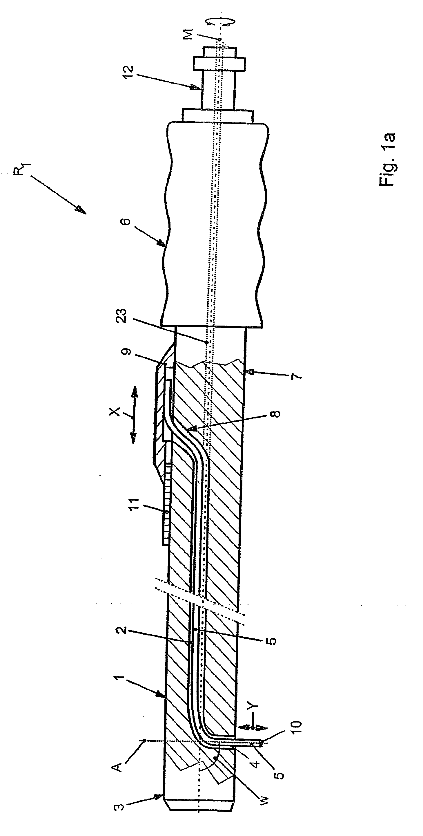
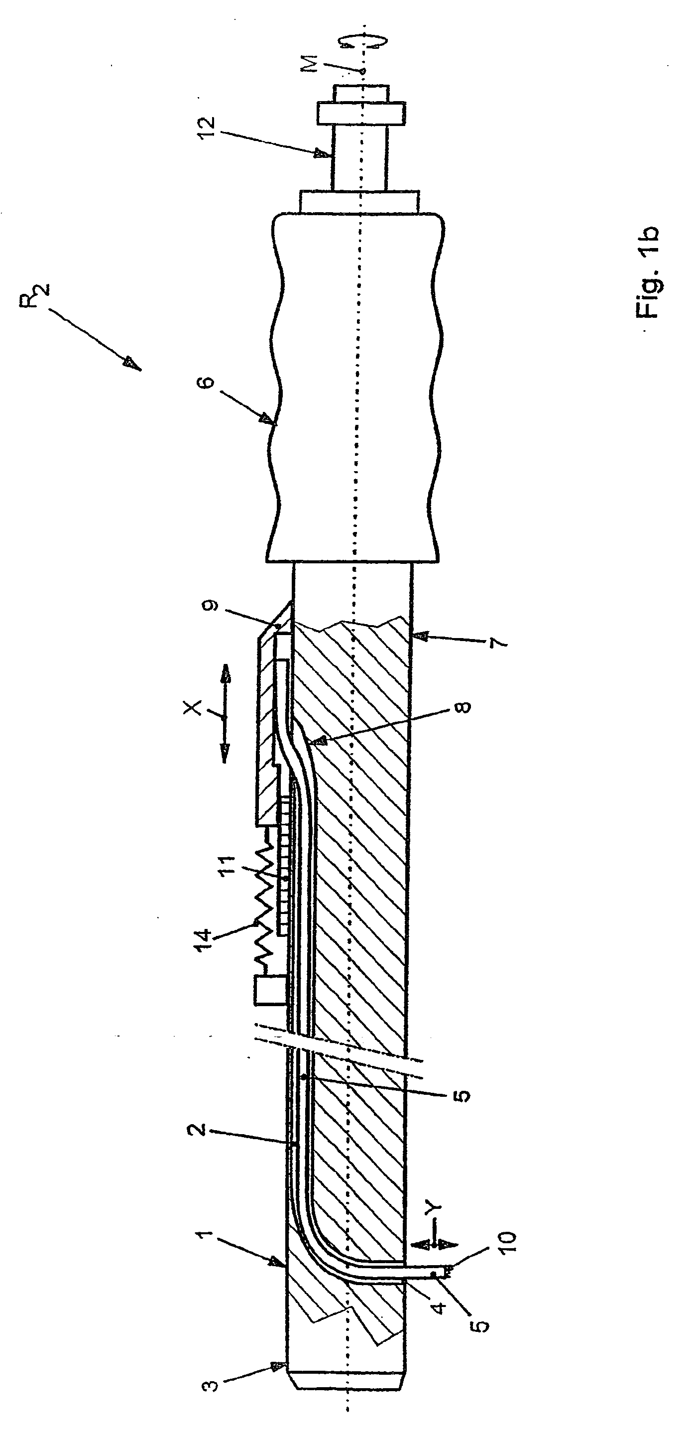
[0021] According to FIG. 1a, an internal saw R1 according to the invention has a base body 1 in which a saw blade 5, preferably of rectangular cross section, is guided axially, preferably centrally, in a guide 2, and emerges radially from an outlet opening 4 in a head area 3 of the base body 1. At the other end of the head area 3, near to a grip element 6, an insertion shaft 8 serving for insertion of the saw blade 5 is formed on an outer jacket surface 7, preferably opposite to the outlet opening 4, in the base body 1. The saw blade 5 can be connected permanently or releasably to an operating element 9 or can be permanently connected, and the saw blade 5 can be moved radially out of the head area 3 of the base body 1 by movement of the operating element 9 along the double arrow direction X shown. At the front end, the saw blade 5 is provided, as can be seen in particular in FIG. 5, with a plurality of teeth 10 which are arranged in an arc shape, for example, in the front end area. ...
PUM
 Abstract
Description
Claims
Application Information