Enhanced locomotive adhesion control

a technology of adhesion control and locomotives, applied in the direction of process and machine control, tractors, instruments, etc., can solve the problems of the response time of the locomotive to a change, and achieve the effect of reducing the response time and rapid adjustment of the operation

Inactive Publication Date: 2005-03-24
GENERAL ELECTRIC CO
View PDF12 Cites 22 Cited by
  • Summary
  • Abstract
  • Description
  • Claims
  • Application Information

AI Technical Summary

Benefits of technology

Briefly stated, the present invention is directed to a traction control system for a railroad locomotive to reduce the response time to changed operating conditions so to maintain the locomotive's tractive effort at a maximum level. The system achieves this by determining when an axle is producing at or near its maximum t...

Problems solved by technology

A problem with current control systems is t...

Method used


Image

  • Enhanced locomotive adhesion control
  • Enhanced locomotive adhesion control
  • Enhanced locomotive adhesion control

Examples


Embodiment Construction

The following detailed description illustrates the invention by way of example and not by way of limitation. The description clearly enables one skilled in the art to make and use the invention, describes several embodiments, adaptations, variations, alternatives, and uses of the invention, including what is presently believed to be the best mode of carrying out the invention.

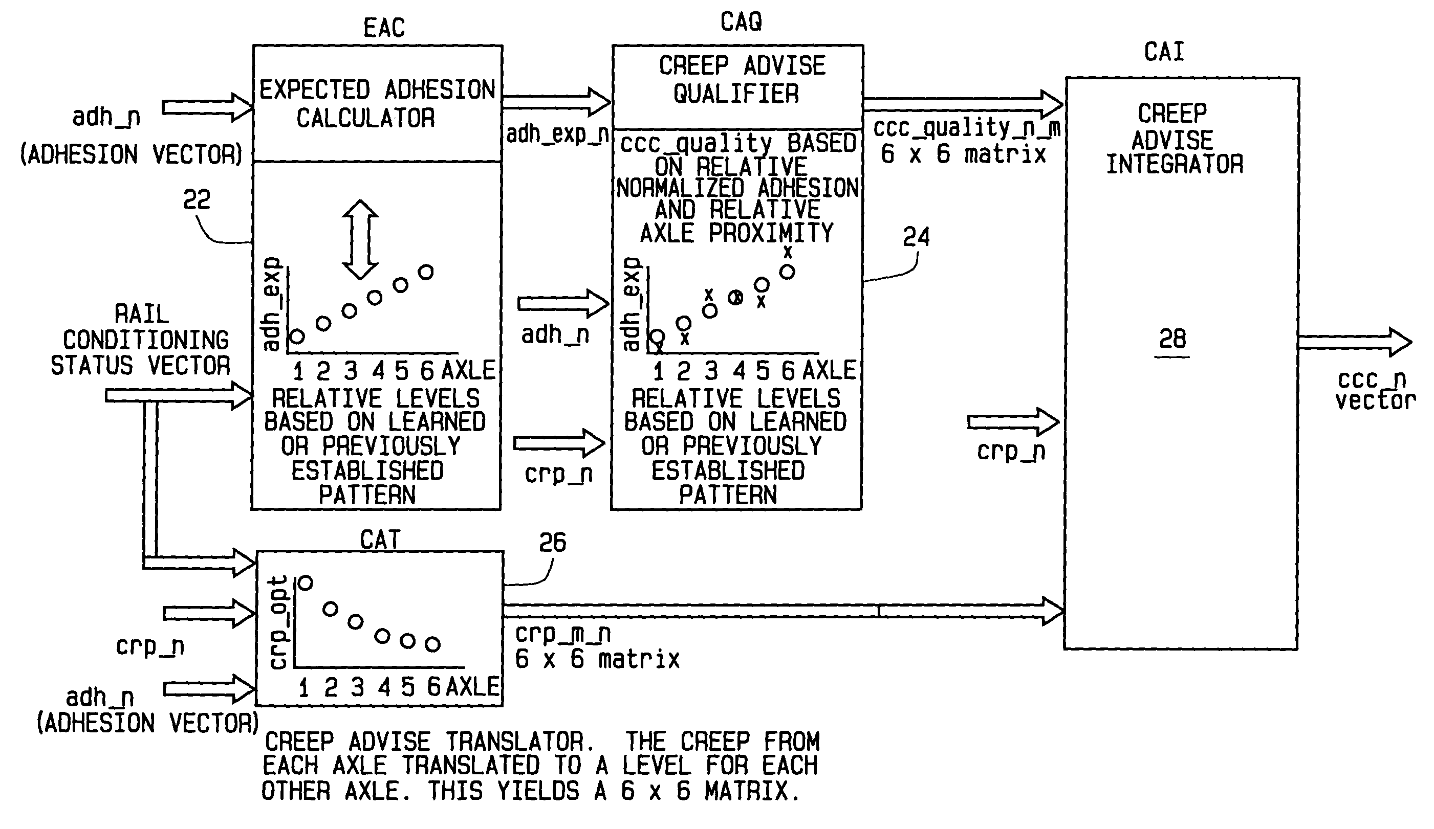
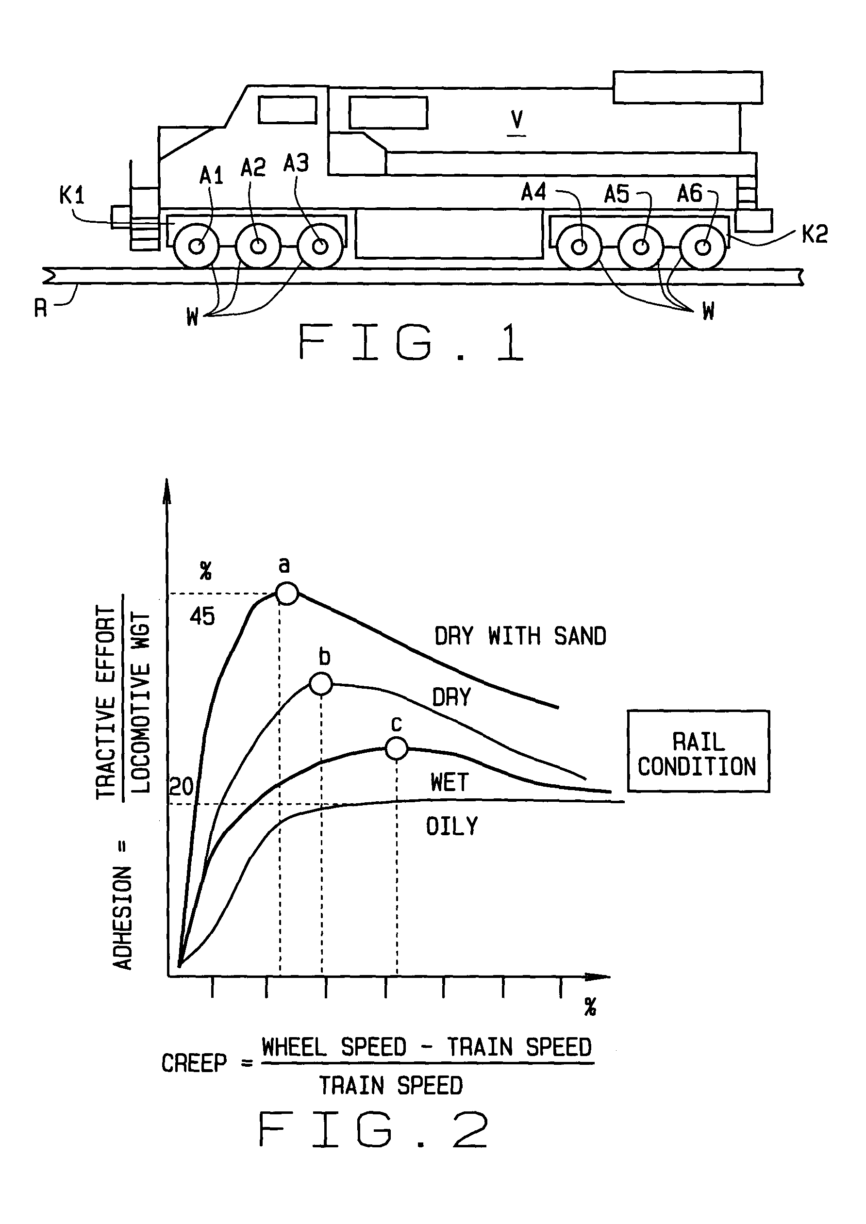
Referring to the drawings, as previously described with respect to FIG. 1, a railroad locomotive V has a forward truck K1 and rearward track K2. Each truck supports three axles A1-A3 and A4-A6 respectively. An improved traction control system of the present invention is indicated generally 10 in FIG. 7. System 10 includes a coupled creep control unit (CCC) 12, which, for the locomotive of FIG. 1, is for a six axle locomotive having individual axle creep control. For this purpose, each axle has an associated tractive effort maximizer TEM1-TEM6 respectively. Control unit 12 supplies a separate signal to each m...


PUM


Abstract

A method of dynamically controlling traction of a locomotive (V) having a plurality of axles (A1-A6) on each of which are mounted wheels (W) for moving the locomotive over a set of rails (R). A creep control signal (creep_n) is provided to a controller (TMTC) for each axle to move the locomotive over the rails, the creep control signal being a function of adhesion operation characteristics (tractive effort, torque, creep) for that axle. An advisory signal (ccc_n) combining values representative of the adhesion quality of the two axles is provided to the controller to maximize the tractive effort of the axle if the adhesion quality of the other axle is a maximum for the current rail conditions. This reduces the amount of time for the axle to attain its maximum tractive effort when rail conditions change.

Description

CROSS-REFERENCE TO RELATED APPLICATIONS None. STATEMENT REGARDING FEDERALLY SPONSORED RESEARCH OR DEVELOPMENT Not Applicable. BACKGROUND OF THE INVENTION This invention relates to traction control of railroad locomotives; and more particularly, to a system and method of enhancing locomotive adhesion control using creep and adhesion measurements of all the axles, and the proximity of an axle to each of the other axles to affect the adhesion of each individual axle. Railroad locomotives must provide a great degree of traction under a wide range of rail conditions; i.e., dry, wet, icy, oily. Generating the maximum tractive effort of a locomotive, or a consist of locomotives, produces the most efficient and effective operation of the train. Developing the maximum tractive effort by a locomotive requires that each axle of the locomotive, which includes the traction motor and wheels associated with the axle, develops its maximum tractive effort. In a moving train, developing the maxi...

Claims


Application Information

Patent Timeline
IPC IPC(8): B61C15/14
CPCB61C15/14
Inventor KUMAR, AJITH K.WORDEN, BRET
Owner GENERAL ELECTRIC CO
Why Eureka
Try Eureka