Shoe insert pad

a technology for inserting pads and shoes, applied in the direction of uppers, soles, insoles, etc., can solve the problems of affecting the service life of the car, and requiring constant repair and collapse rituals

Inactive Publication Date: 2005-03-31
PEOPLES WHEAD GORDON
View PDF11 Cites 12 Cited by
  • Summary
  • Abstract
  • Description
  • Claims
  • Application Information

AI Technical Summary

Benefits of technology

[0013] It is an object of the present invention to provide a shoe insert pad that provides comfortable support for the carriage system of a human body.

Problems solved by technology

As a result without any kind of long term protection the carriage system must go through a constant ritual of collapse and repair.
Also persons who must work while constantly on their feet can suffer possible random long term injuries to parts of the carriage system. when the spine itself is the affected part the end results can be far reaching.
The problem with many of these products is that they lose their resilience early on and cease to offer effective resistance to impact providing only limited support to the carriage system in the long term.
Additionally, some products can be very expensive.

Method used


Image

  • Shoe insert pad
  • Shoe insert pad

Examples


Embodiment Construction

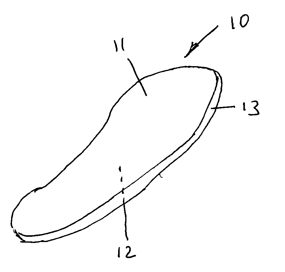
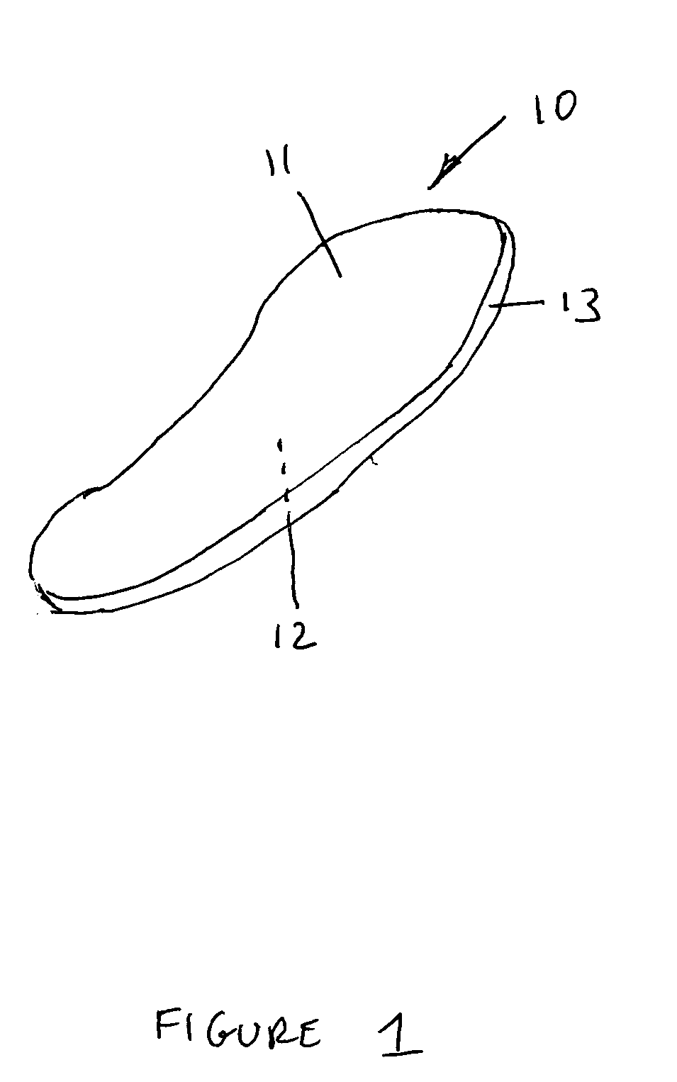
[0022] Referring now to the drawing, and in particular to FIG. 1, there is shown a shoe insert pad 10. The shoe insert pad 10 includes a first planar surface 11 and a second planar surface 12 opposite the first planar surface 11.

[0023] The first planar surface 11 and the second planar surface 12 are shaped substantially in the shape of a human foot. Additionally, the first planar surface 11 and the second planar surface 12 are defined by an edge 13. The edge 13 may be of varying thickness, but in a preferred embodiment of the present invention, the edge 13 of the shoe insert pad 10 is {fraction (3 / 16)} inches thick.

[0024] In a preferred embodiment of the present invention, the shoe insert pad 10 is formed of a rigid foam material, specifically a polyethylene vinyl acetate (EVA) material. However, other materials known to one of ordinary skill in the art may be used to form the shoe insert pad 10 without departing from the scope and spirit of the invention. The EVA material will ha...


PUM

PropertyMeasurementUnit
densityaaaaaaaaaa
densityaaaaaaaaaa
thicknessaaaaaaaaaa

Abstract

A shoe insert pad is disclosed. The shoe insert pad includes a first planar surface and a second planar surface, wherein the first and second planar surfaces are defined by a shoe insert pad, comprising: a first planar surface; a second planar surface; and an edge defining the first planar surface and second planar surface substantially in the shape of a human foot; wherein the shoe insert pad is formed of a polyethylene vinyl acetate material having a density between 8 and 9 pounds per cubic foot.

Description

FIELD OF THE INVENTION [0001] The present invention relates to insert pads for shoes, and in particular to a foam shoe insert that is long lasting and provides increased comfort. BACKGROUND OF THE INVENTION [0002] Over time, the kinetic force of daily walking plus just standing and shifting one's weight from one foot to the other places the human frame into a compromising position. The human frame is referred to here as the “carriage system” The carriage system is comprised of the soft pads of the heels and soles of the feet, hips, lower back, spine, knee joints, arches, toes, small bones and ankles. As a result without any kind of long term protection the carriage system must go through a constant ritual of collapse and repair. This quite naturally contributes to the aging process of this system and to the early break down of weak points within the system due to personal genetics. Also persons who must work while constantly on their feet can suffer possible random long term injurie...

Claims


Application Information

Patent Timeline
Patent Type & Authority Applications(United States)
IPC IPC(8): A43B17/14
CPCA43B17/14
Inventor PEOPLES, WHEAD GORDON
Owner PEOPLES WHEAD GORDON
Why Eureka
Try Eureka