Asymmetric honeycomb wall-flow filter having improved structural strength

a honeycomb wall and filter technology, applied in the direction of ceramic extrusion dies, chemical/physical processes, machines/engines, etc., can solve the problems of ash particles, unable to be removed by thermal regeneration, and ash particles are not combustible, so as to achieve substantially uniform width of discharge slots and large cross-sectional area

Active Publication Date: 2005-03-31
CORNING INC
View PDF29 Cites 34 Cited by
  • Summary
  • Abstract
  • Description
  • Claims
  • Application Information

AI Technical Summary

Benefits of technology

The invention is about a special extrusion die used to make honeycomb filters. The die has two different regions: a central region with many small slits and a peripheral region with at least one larger slit. The central region has many small feedholes that connect to the slits. The extrusion die also has a skin forming mask that creates a skin slot that connects to the larger slit. This design helps to make filters with uniform pore size and can improve the production process.

Problems solved by technology

The technical problem addressed in this patent is how to improve the storage capacity of honeycomb filters without reducing their structural strength, while maintaining good flow rates through the filter. This is important because frequent thermal regeneration can damage the filter and increase back pressure on the engine, leading to decreased engine performance. The solution proposed involves making the hydraulic diameter of the inlet cells larger than that of the outlet cells, which increases the effective surface area available for collecting soot and ash particles and ultimately increases the overall storage capacity of the honeycomb filter. However, this modification may make the filter more susceptible to thermal shock and cracking during thermal regeneration.

Method used


Image

  • Asymmetric honeycomb wall-flow filter having improved structural strength
  • Asymmetric honeycomb wall-flow filter having improved structural strength
  • Asymmetric honeycomb wall-flow filter having improved structural strength

Examples


Embodiment Construction

The invention will now be described in detail with reference to a few preferred embodiments, as illustrated in the accompanying drawings. In the following description, numerous specific details are set forth in order to provide a thorough understanding of the invention. It will be apparent, however, to one skilled in the art that the invention may be practiced without some or all of these specific details. In other instances, well-known features and / or process steps have not been described in detail in order to not unnecessarily obscure the invention. The features and advantages of the invention may be better understood with reference to the drawings and discussions that follow.

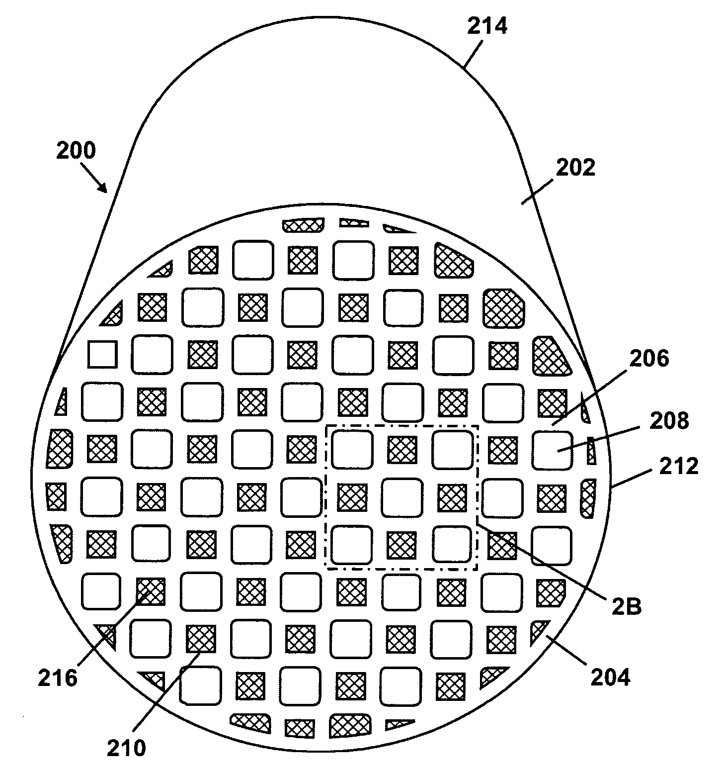
For illustration purposes, FIG. 2A shows a honeycomb wall-flow filter 200 according to an embodiment of the invention. The honeycomb filter 200 has a columnar body 202 whose cross-sectional shape is defined by a skin (or peripheral wall) 204. The profile of the skin 204 is typically circular or elliptical,...


PUM

PropertyMeasurementUnit
Thicknessaaaaaaaaaa
Thicknessaaaaaaaaaa
Thicknessaaaaaaaaaa

Abstract

A honeycomb filter includes an array of interconnecting porous walls which define an array of first channels and second channels. The first channels are bordered on their sides by the second channels and have a larger hydraulic diameter than the second channels. The first channels have a square cross-section, with corners of the first channels having a shape such that the thickness of the porous walls adjoining the corners of the first channels is comparable to the thickness of the porous walls adjoining edges of the first and second channels.

Description


Claims


Application Information

Patent Timeline
Owner CORNING INC
Why Eureka
Try Eureka