Cylinder with internal pushrod

Inactive Publication Date: 2005-03-31
CATERPILLAR INC
View PDF13 Cites 62 Cited by
  • Summary
  • Abstract
  • Description
  • Claims
  • Application Information

AI Technical Summary

Benefits of technology

[0008] According to a further aspect of the invention, a method for actuating a fluid actuator including a cylinder body with an internal cavity therein, and a piston and rod assembly having an axial passage extending therein and disposed for axial movement within the internal cavity of the cylinder body may be provided. The method may include creating a first urging force on the piston and rod assembly in an axial direction by directing pressurized fluid from a fluid sourc

Problems solved by technology

Each time the work implement is raised, potential energy is created within the work implement system, and each time the work implement is lowered by releasing pressure from the cylinder, the potential energy is lost.
Prior systems may suffer from various disadvantages.
For example, adding additional separate cylinders to a lift system may increase the cost of the lift system.
Moreover, application of additional cylinders to an existing lif

Method used


Image

  • Cylinder with internal pushrod
  • Cylinder with internal pushrod
  • Cylinder with internal pushrod

Examples


Embodiment Construction

[0018] Reference will now be made in detail to embodiments or features of the invention, examples of which are illustrated in the accompanying drawings. Wherever possible, the same or corresponding reference numbers will be used throughout the drawings to refer to the same or corresponding parts.

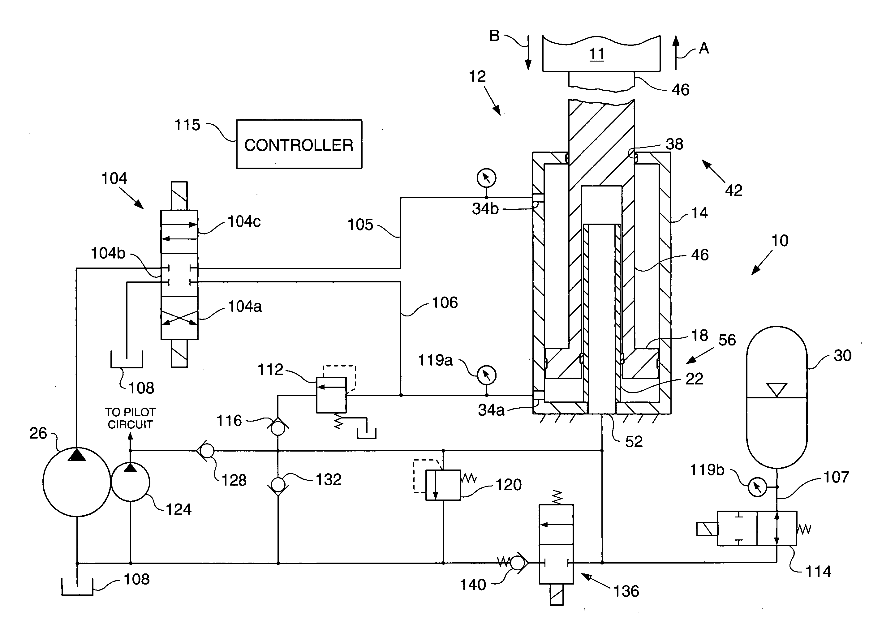
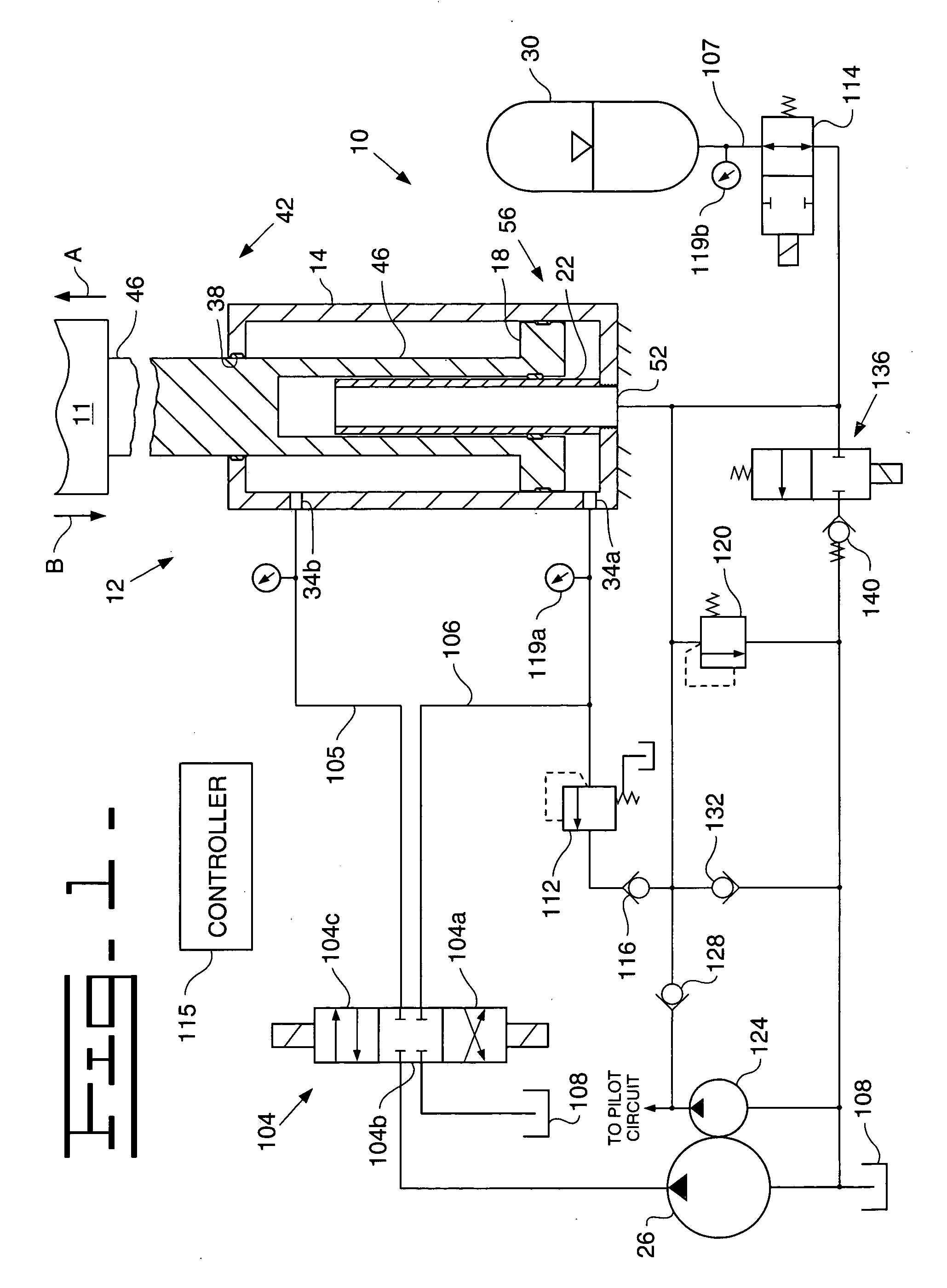
[0019] Referring to FIG. 1, an exemplary fluid actuation system 10 is shown. The fluid actuation system 10 may be used, for example, on earthworking machines, such as loaders, excavators, mining shovels, or the like, to, for example, lift and lower a work implement (generally indicated with reference number 11 in FIG. 1), which may be attached to the piston and rod assembly 18 of the actuation system 10. The fluid actuation system 10 may include a cylinder arrangement 12 having a cylinder body 14, a piston and rod assembly 18 disposed within the cylinder body 14, and a tubular element 22. The system 10 may further include a first source of pressurized fluid 26, and a second source of pressu...


PUM


Abstract

A cylinder assembly is disclosed. The cylinder assembly may include a cylinder body having an internal cavity therein and a piston and rod assembly disposed for axial movement within the internal cavity of the cylinder body. The piston and rod assembly may have an axial passage extending therein. The cylinder assembly may further include a tubular element received within the axial passage of the piston and rod assembly. At least a portion of the tubular element may extend out of the axial passage and into the internal cavity of the cylinder body between the axial passage and a wall of the cylinder body.

Description

TECHNICAL FIELD [0001] The present invention relates generally to fluid actuators and, more particularly, to fluid-actuated cylinders. BACKGROUND [0002] Many work machines, such as earthworking machines or the like, include fluid actuators, such as hydraulic cylinders, which may be used by the earthworking machines to lift, lower, or otherwise move earthworking equipment. Such fluid actuators may experience many extension-retraction cycles during a work period. For example, a hydraulic cylinder on an earthworking machine may be used to periodically lift and lower a work implement. The work implement may be raised by applying pressurized fluid to the hydraulic cylinder, and the work implement may be lowered under its own weight by releasing the pressure supplied by the fluid. Again, the work implement may be raised by applying pressurized fluid to the cylinder, and again the work implement may be lowered by releasing the fluid from the cylinder. Each time the work implement is raised...

Claims


Application Information

Patent Timeline
IPC IPC(8): E02F9/22F15B1/02F15B11/036F15B15/14
CPCE02F9/2217F15B2211/88F15B11/036F15B15/1466F15B2211/20538F15B2211/20584F15B2211/20592F15B2211/212F15B2211/30505F15B2211/30525F15B2211/3111F15B2211/327F15B2211/40515F15B2211/41527F15B2211/41572F15B2211/426F15B2211/45F15B2211/50518F15B2211/5151F15B2211/5153F15B2211/55F15B2211/6052F15B2211/625F15B2211/6313F15B2211/7055F15B1/024
Inventor AARESTAD, ROBERT A.BRINKMAN, JASON L.HAGEN, PAUL D.KRONE, JOHN J.ROMACK, GEORGE M.
Owner CATERPILLAR INC
Why Eureka
Try Eureka