System and method for deploying a weapon from a stealth position

a technology of deploying a weapon and a stealth position, applied in the field of weapons systems, can solve the problems of retractable roof, electric motor (d.c. or even a.c.) meeting such specifications tend to be expensive, and vehicles are quite expensive, and achieve the effect of deploying a stealth weapon and a system

Inactive Publication Date: 2005-03-31
IBIS TEK
View PDF11 Cites 42 Cited by
  • Summary
  • Abstract
  • Description
  • Claims
  • Application Information

AI Technical Summary

Benefits of technology

[0009] Accordingly, in a first aspect of the invention, a system is provided comprising: a weapon support cage having a frame and a lift platform attached to the frame for raising and lowering a weapon, and having a retractable roof for covering the weapon when the weapon is in its lowered position, and also having means for

Problems solved by technology

The prior art in respect to a cloth retractable roof has one major problem.
Using such a retractable hard roof for a stealth application poses two problems.
Another problem with the prior art—this time generally in respect to the roof but more specifically in respect to the motor used to raise and lower/retract the roof—is that to raise the roof (typically 35 pounds, as noted above) quickly (typically on the order

Method used


Image

  • System and method for deploying a weapon from a stealth position
  • System and method for deploying a weapon from a stealth position
  • System and method for deploying a weapon from a stealth position

Examples


Embodiment Construction

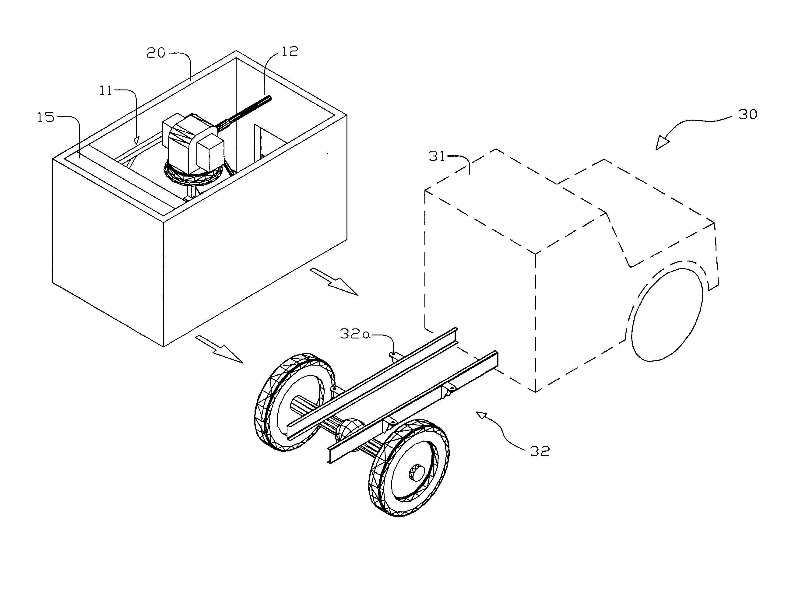
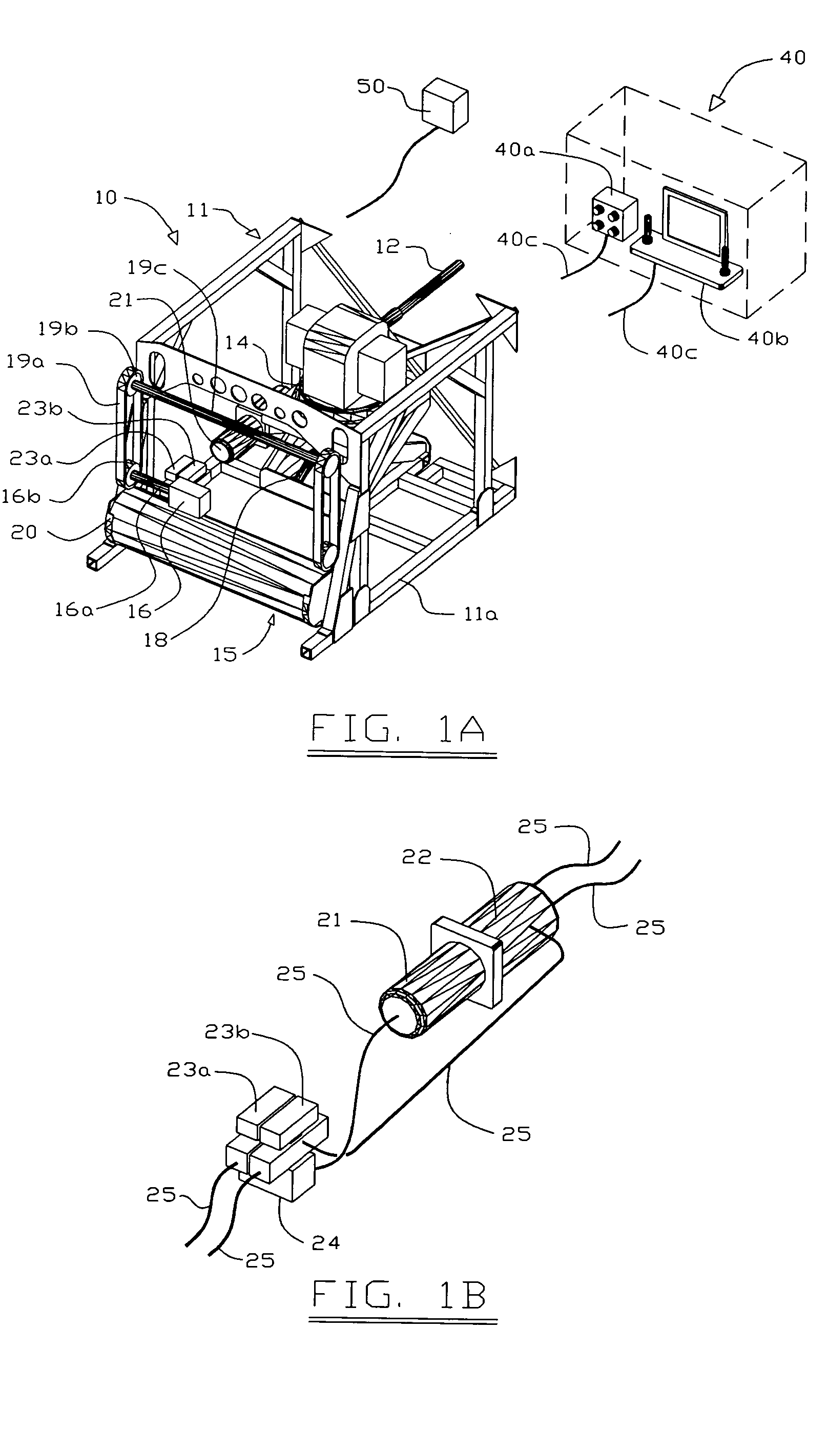
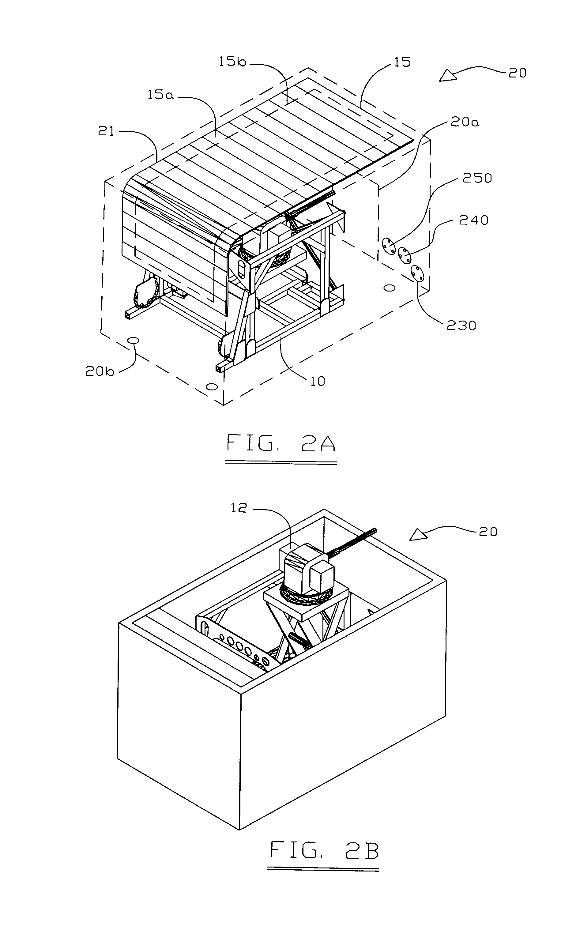
[0022] Referring now to FIGS. 1A and 1B, a weapon module 10 is shown including a weapons support cage 11 having a frame 11a to which is attached a lift platform 14 for raising and lowering a weapon 12 attached to the lift platform. As shown, the weapon module 10 includes a hydraulic motor 16 having a veined structure (not shown), i.e. having in essence a rotor or screw that turns in response to hydraulic fluid from a hydraulic reservoir 22 being forced through connecting hydraulic lines 25 under the urging of an electric pump 21. The turning of the veined structure results in raising or lowering / retracting of a hard roof 15 consisting essentially of spaced apart slats 15a, via coupling of the roof to the hydraulic motor by an arrangement of a drive gear 16b on a shaft 16a turned by the hydraulic motor 16, two timing belts 19a, two corresponding pairs of timing gears 19b, a timing axle 19c connecting one timing gear (the top gear) of each pair, and four sprockets 20 for gripping the ...


PUM


Abstract

A stealth weapon module (10) including a weapon support cage (11) and a weapon (12), with the weapon module (10) able to be stowed beneath a retractable hard roof (15). The roof (15) is raised and lowered by a hydraulic motor (16), and includes a stabilizing cloth (15b) that keeps the roof (15), made of interconnected slats (15a), from pulling apart or otherwise changing shape as it is raised and lowered, even at rates of travel of several inches per second. The weapon module (10), with any of various different roof designs including the retractable hard roof (15), can be incorporated into either a transportable shell (20), able to be moved from one application to another, or can be built into (and so specially adapted to) a structure, such as the back/cab of a sports utility vehicle.

Description

TECHNICAL FIELD [0001] The present invention pertains to a weapon system—such as a turret for a machine gun or a missile launcher—and associated equipment, and more particularly to a machine for raising and lowering a weapon system from a stowed position to a deployed position so as to make the weapon suitable for a stealth mission, and also more particularly to providing an enclosure for a weapon so as to make the weapon suitable for a stealth mission. BACKGROUND ART [0002] Today there are many uses for a stealth weapon, i.e. a weapon normally hidden from view in an enclosure of a type not normally having a weapon, such as the back of a sport utility vehicle or a (covered) cab (back-end) of a pickup truck type vehicle. Such uses include e.g. some homeland defense missions, VIP (very important person) escort, reconnaissance, security patrol, and transport of special cargo (such as nuclear material), or any mission in which it is advantageous to avoid drawing attention to the mission...

Claims


Application Information

Patent Timeline
IPC IPC(8): F41A23/20F41A23/34
CPCF41A23/34F41A23/20
Inventor HELMS, JAMESBUCKNER, THOMAS G.
Owner IBIS TEK
Why Eureka
Try Eureka