Valve assembly having improved conductance control

a technology of conductance control and valve assembly, which is applied in the direction of braking systems, machines/engines, transportation and packaging, etc., can solve the problems of poor control of flow (conductance) and poor conductance control in the operating range of the valve, and achieve improved conductance control, increased conductance, and improved conductance control

Inactive Publication Date: 2005-03-31
MKS INSTR INC
View PDF15 Cites 97 Cited by
  • Summary
  • Abstract
  • Description
  • Claims
  • Application Information

AI Technical Summary

Benefits of technology

[0011] According to one exemplary embodiment, the second surface of the seal ring includes a continuous annular sealing portion for contacting the slide plate when the seal ring is biased against the slide plate so that a fluid-tight seal can be formed between the continuous annular sealing portion and the slide plate, and at least one passageway positioned between the annular sealing portion and the second side for increasing conductance between the seal ring and the slide plate during movement of the slide plate with respect to the seal ring.
[0012] Among other aspects and advantages, the valve assembly of the present invention provides a pendulum valve assembly that includes passageways for providing additional conductance control near the minimum controllable conductance position of the slide plate. In particular, the passageways are provided in the seal ring to provide improved conductance control when the slide plate is moved towards the seal ring upon the valve being opened. The passageways beneficially provide the improved conductance without requiring an increase in the flange-to-flange dimension of the valve assembly.
[0013] According to another exemplary embodiment, a surface of the slide plate facing the seal ring includes a continuous annular sealing portion for contacting the seal ring when the seal ring is biased against the slide plate so that a fluid-tight seal can be formed between the continuous annular sealing portion and the seal ring, and at least one passageway positioned between the annular sealing portion and a radially outer side of the slide plate for increasing conductance between the seal ring and the slide plate during movement of the slide plate with respect to the seal ring.
[0014] According to a further exemplary embodiment, the valve assembly is provided without the seal ring and one of the slide plate and the annular surface of the housing includes at least one passageway for increasing conductance between the slide plate and the annular surface during movement of the slide plate.

Problems solved by technology

One drawback for some existing gate or pendulum valves is that the valve provides poor control of flow (conductance) during the initial opening of the valve.
Thus, the overall conductance includes very little change in conductance followed by a very rapid change in conductance (and vice versa as the gate is closed), which results in poor control of conductance in this operating range of the valve.

Method used


Image

  • Valve assembly having improved conductance control
  • Valve assembly having improved conductance control
  • Valve assembly having improved conductance control

Examples


Embodiment Construction

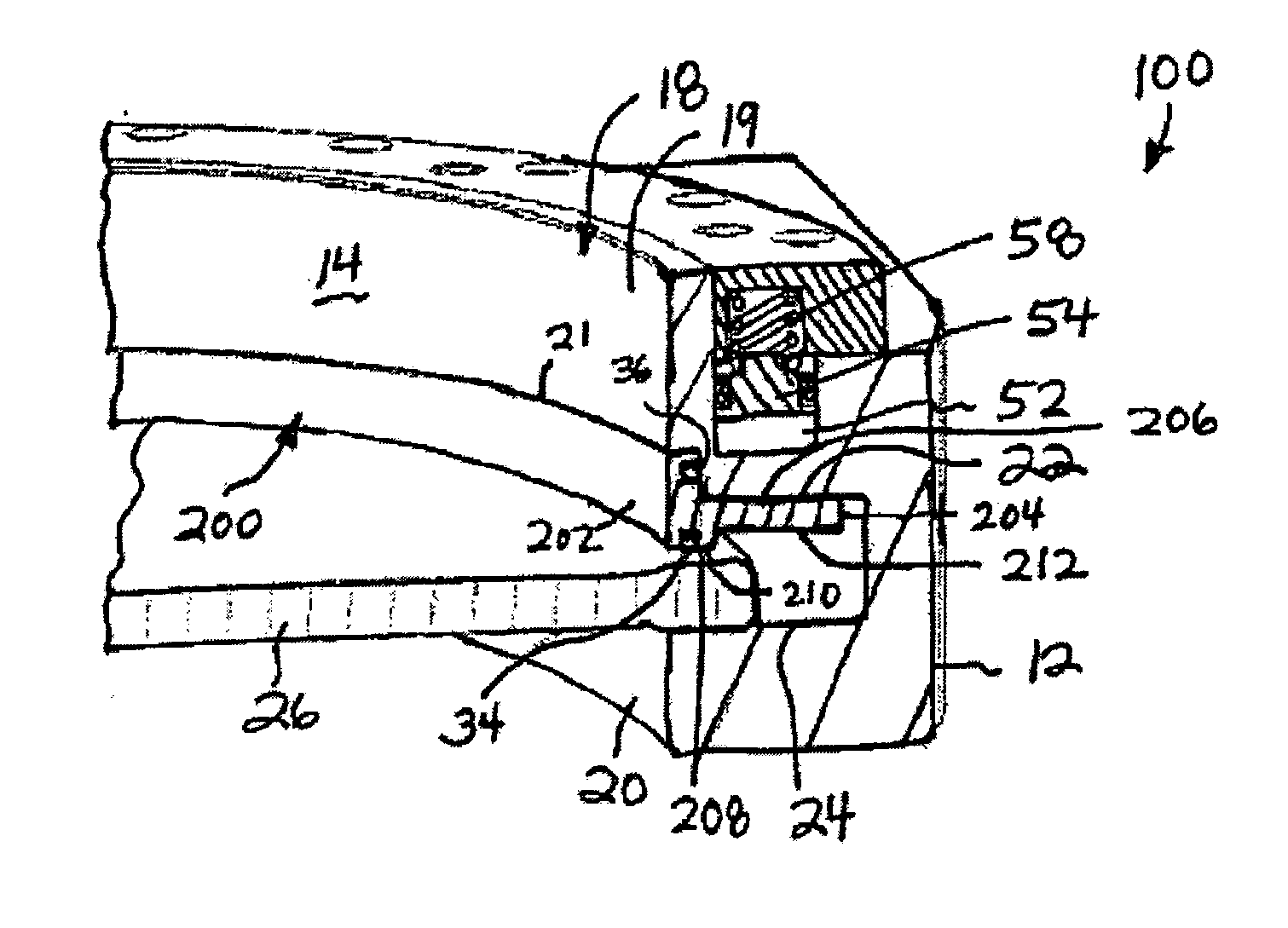
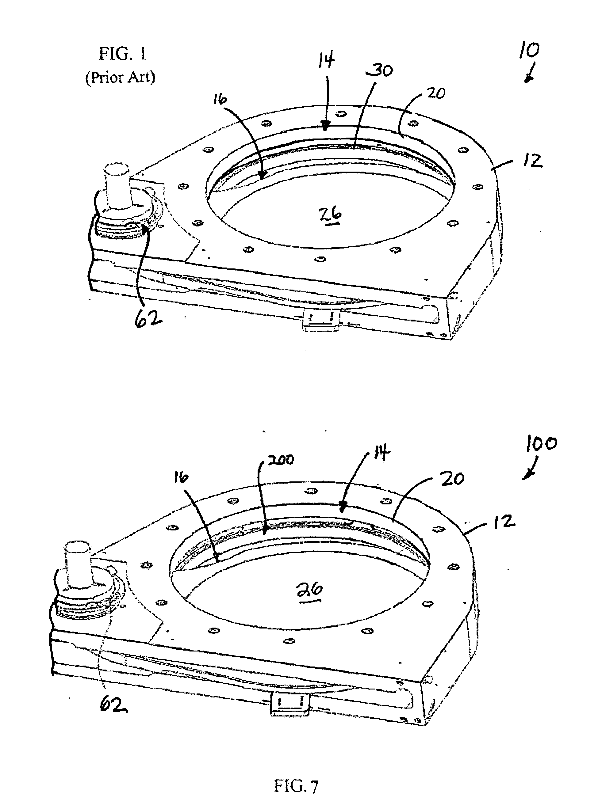
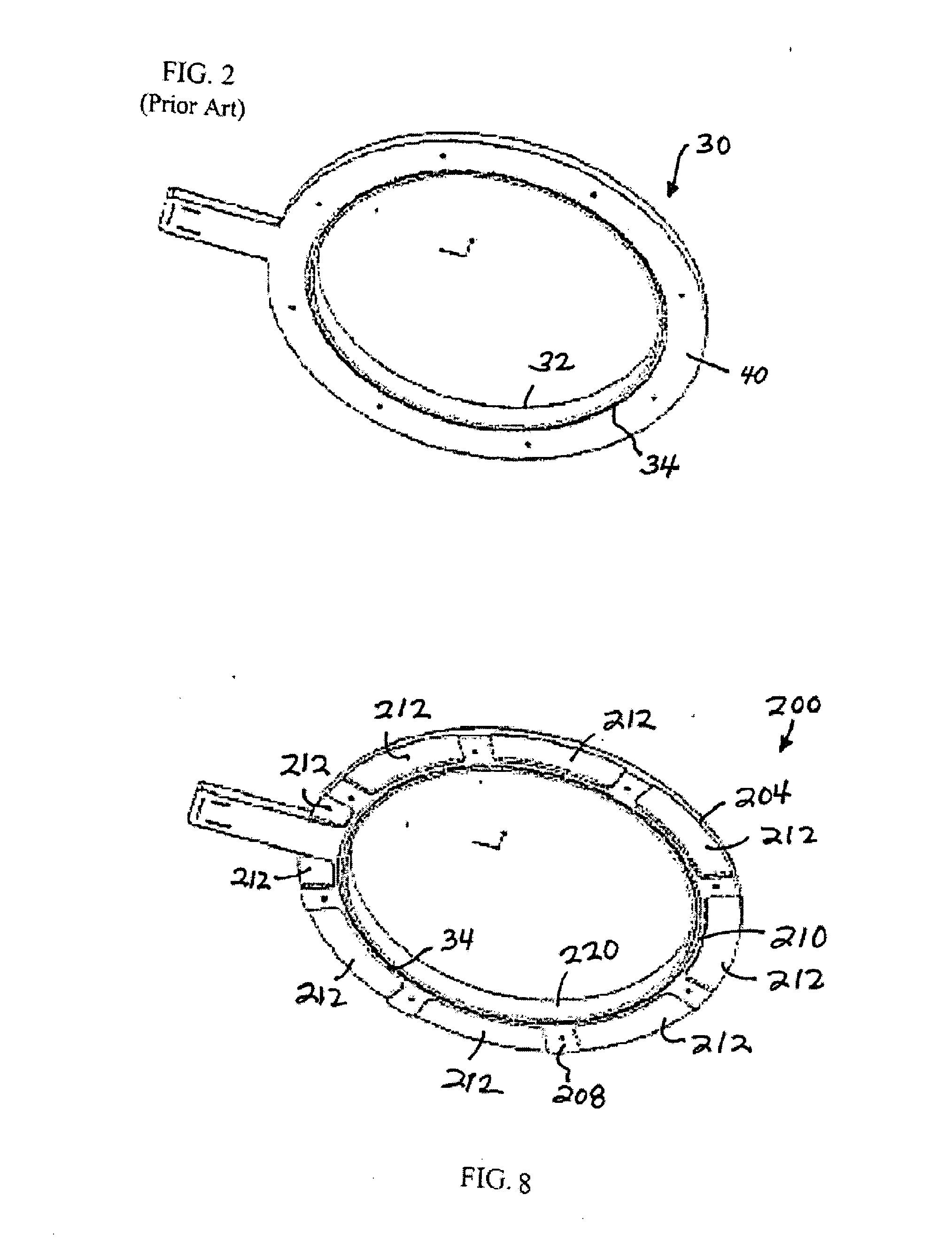
[0034] Referring to FIGS. 1, 3 and 4, an exemplary embodiment of a pendulum valve assembly 10 constructed in accordance with the prior art generally includes a housing 12 defining a flow path 14 extending between an inlet 18 and an outlet 20. Valve seats 22, 24 are provided in the flow path 14 of the housing 12 around edges of the openings 18, 20. As shown, the assembly includes a pendulum valve 16 operatively mounted within the housing and having a slide plate 26 which is pivotally movable between a first opened position completely out of the flow path 14, and a second opened position, which is inside the flow path 14, as shown in FIG. 3. The slide plate 26 allows reduced fluid flow through the outlet 20 when in the second opened position inside the flow path 14. The slide plate 26 is further laterally, or axially, movable from the second opened position inside the flow path 14 to a minimum controllable conductance position against the valve seat 24 of the outlet 20, as shown in FI...


PUM


Abstract

A valve assembly including a housing having a flow channel and an annular surface surrounding the flow channel, a slide plate movable to a closed position, and a seal ring positioned between the annular surface and the slide plate. The seal ring includes a first and second sides, a first surface extending between the first and the second sides and facing towards the annular surface of the housing, and a second surface axially spaced from the first surface and extending between the first and the second sides and facing towards the slide plate. The second surface includes a continuous annular sealing portion for contacting the slide plate when the seal ring is biased against the slide plate so that a fluid-tight seal can be formed between the continuous annular sealing portion and the slide plate, and at least one passageway positioned between the annular sealing portion and the second side.

Description

FIELD OF THE INVENTION [0001] The present invention relates generally to valve assemblies and, more particularly, to a new and improved valve assembly including passageways that provide improved conductance control. BACKGROUND OF THE INVENTION [0002] A slide or gate valve assembly generally includes a housing defining a flow path extending between an inlet and an outlet. The slide valve assembly can, for example, be connected between a process chamber and a vacuum pump to form a portion of a high purity gas delivery system, such as those used in semiconductor manufacturing or other thin film coating processes performed at very low pressures (high vacuums), e.g., a pressure on the order of one torr or less. In such a case, a flange of the inlet of the valve assembly is secured to the process chamber while a flange of the outlet of the valve assembly is secured to the vacuum pump. [0003] The slide valve assembly includes a slide plate that laterally moves, with respect to an axis of t...

Claims


Application Information

Patent Timeline
Patent Type & Authority Applications(United States)
IPC IPC(8): F16K3/06
CPCF16K3/06F16K3/02
Inventor LUCAS, PAUL D.CARBONE, ANTHONY J.
Owner MKS INSTR INC
Why Eureka
Try Eureka