Plasma display panel assembly

a technology of display panels and plasma, which is applied in the direction of television systems, gas exhaustion means, and discharge tubes luminescnet screens, etc., can solve the problems of increased production costs and easy breakage of exhaust pipes, and achieve the effect of easy and inexpensive manufacturing

Inactive Publication Date: 2005-03-31
SAMSUNG SDI CO LTD
View PDF16 Cites 21 Cited by
  • Summary
  • Abstract
  • Description
  • Claims
  • Application Information

AI Technical Summary

Benefits of technology

[0013] It is therefore an object of the present invention to provide an improved structure for a PDP.
[0014] It is also an object to provide a design for a PDP that both protects the exhaust pipe and is easy and inexpensive to manufacture.

Problems solved by technology

The exhaust pipe is a part of the panel, but because the exhaust pipe protrudes outward, the exhaust pipe is susceptible to being broken.
However, the conventional shroud device for an exhaust pipe has the complex manufacturing process described above.
Also, because separate first and second shroud areas have to be provided and installed on the portion where the exhaust pipe is formed, there is an increase in the production costs.

Method used


Image

  • Plasma display panel assembly
  • Plasma display panel assembly
  • Plasma display panel assembly

Examples


Embodiment Construction

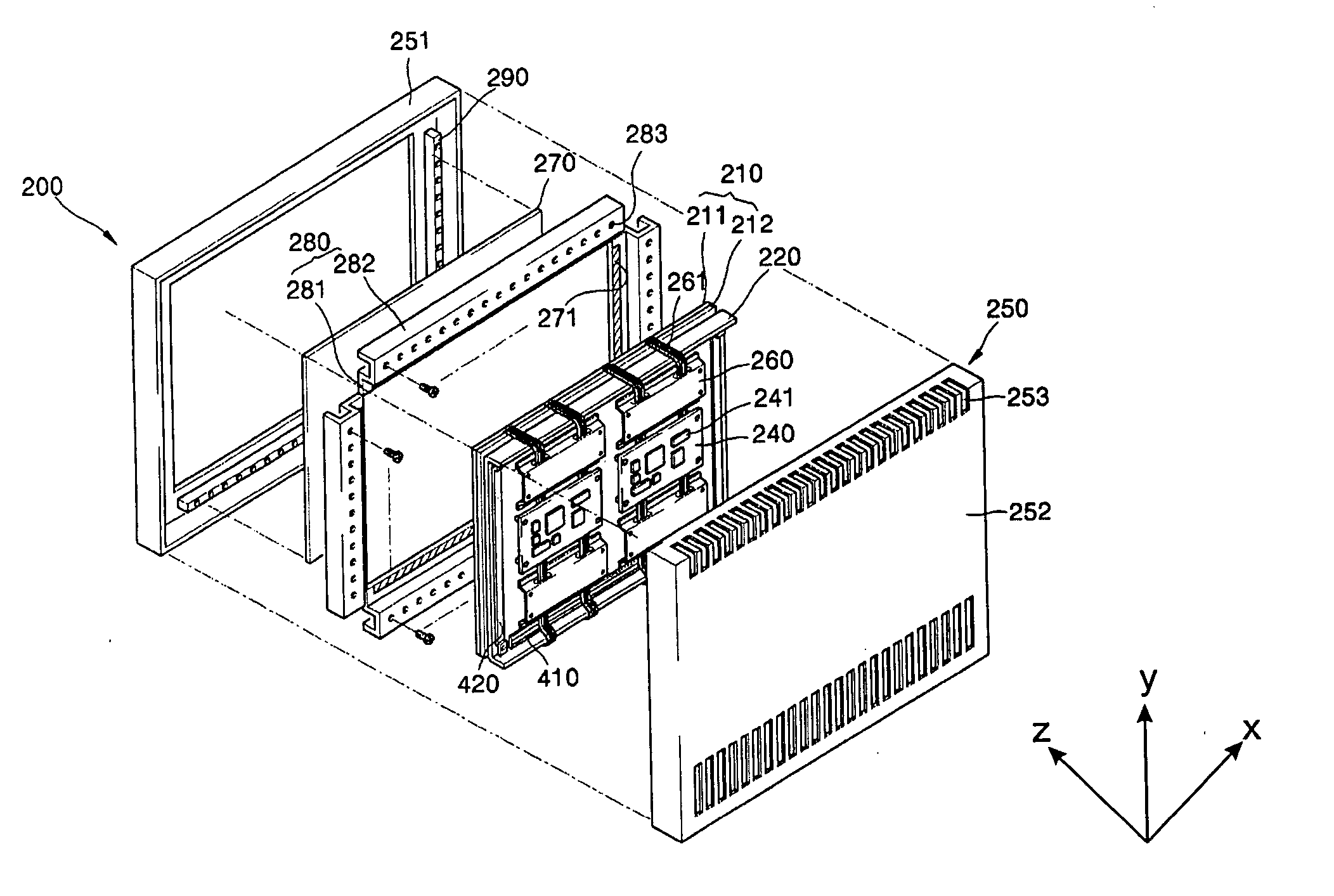
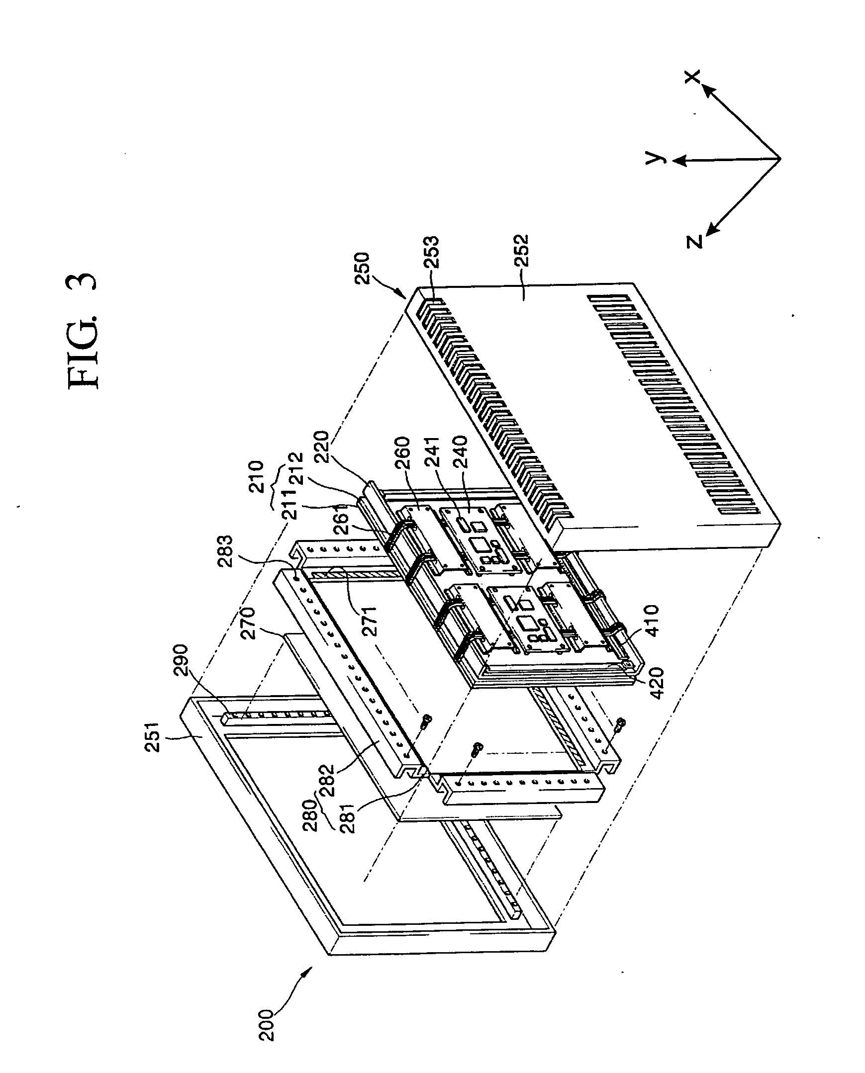
[0024] Turning now to FIG. 3, FIG. 3 is an exploded perspective view of a PDP assembly 200 according to an embodiment of the present invention. Referring to FIG. 3, a PDP assembly 200 includes a panel assembly 210, a chassis base 220 arranged substantially parallel to the panel assembly 210, a heat conduction medium 230 (refer to FIG. 4) interposed between the panel assembly 210 and the chassis base 220 and adhering the chassis base 220 to the panel assembly 210, a driving circuit unit 240 installed on the back of the chassis base 220 and electrically connected by the panel assembly 210 to drive the panel assembly 210, a filter assembly 270 installed at the front of the panel assembly 210, and a case 250 accommodating the panel assembly 210, the chassis base 220, the driving circuit unit 240 and the filter assembly 270.

[0025] The panel assembly 210 includes a front panel 211 and a rear panel 212 that is combined with the front panel 211. The front panel 211 includes an X electrode,...


PUM


Abstract

A plasma display panel (PDP) has an exhaust pipe protruding from a panel assembly, a chassis base mounted on one side of the panel assembly to support the panel assembly such that the exhaust pipe protrudes through a hole formed in the chassis base. A reinforcement structure is mounted on the chassis base to fortify the chassis base and to prevent torque and bending of the panel assembly. A protection structure is designed to form a space to enclose the exhaust pipe to prevent damage to the exhaust pipe. The protection structure is formed to be integral with the reinforcement structure.

Description

CLAIM OF PRIORITY [0001] This application makes reference to, incorporates the same herein, and claims all benefits accruing under 35 U.S.C. § 119 from an application for PLASMA DISPLAY PANEL ASSEMBLY earlier filed in the Korean Intellectual Property Office on Sep. 25, 2003 and there duly assigned Serial No. 2003-66500. BACKGROUND OF THE INVENTION [0002] 1. Field of the Invention [0003] The present invention relates to a plasma display panel assembly, and more particularly, to a plasma display panel that is easy to manufacture due to a simple structure that protects an exhaust pipe formed on a substrate. [0004] 2. Description of the Related Art [0005] Generally, a plasma display panel (PDP) assembly is a flat display device in which a plurality of electrodes are formed opposite to a plurality of substrates, and a predetermined voltage is applied across an electric discharge area between the substrates that is injected with an electric discharge gas so that an image is formed by ligh...

Claims


Application Information

Patent Timeline
IPC IPC(8): H01J17/49F02B63/00
CPCH01J11/54H01J11/10H01J17/16H04N5/645
Inventor KIM, DOO-YOUNG
Owner SAMSUNG SDI CO LTD
Why Eureka
Try Eureka