

Liquid supply system and apparatus incorporating the same
- Summary
- Abstract
- Description
- Claims
- Application Information
AI Technical Summary
Benefits of technology
Problems solved by technology
Method used
Image

Examples
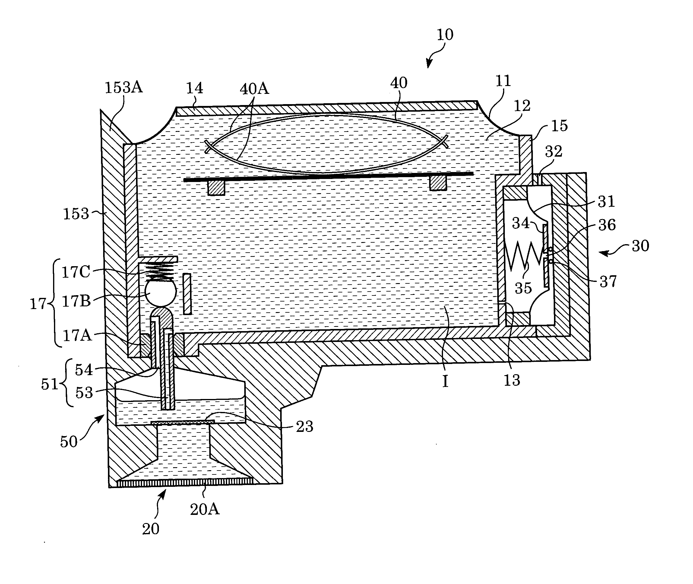
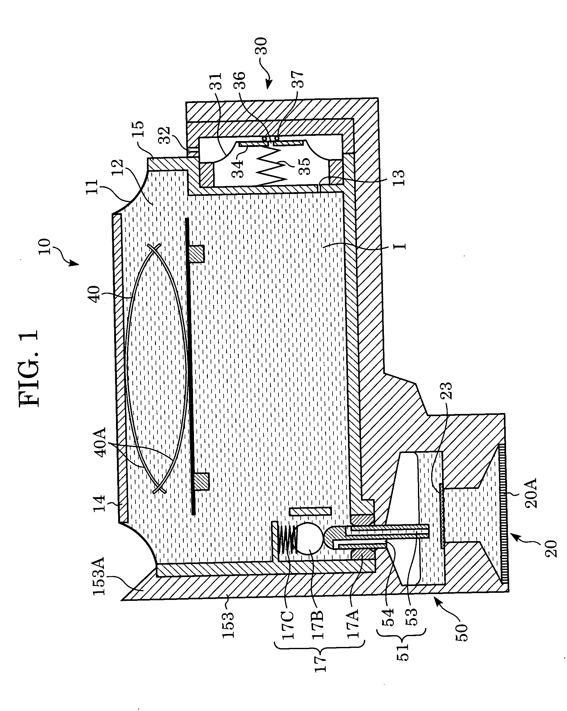
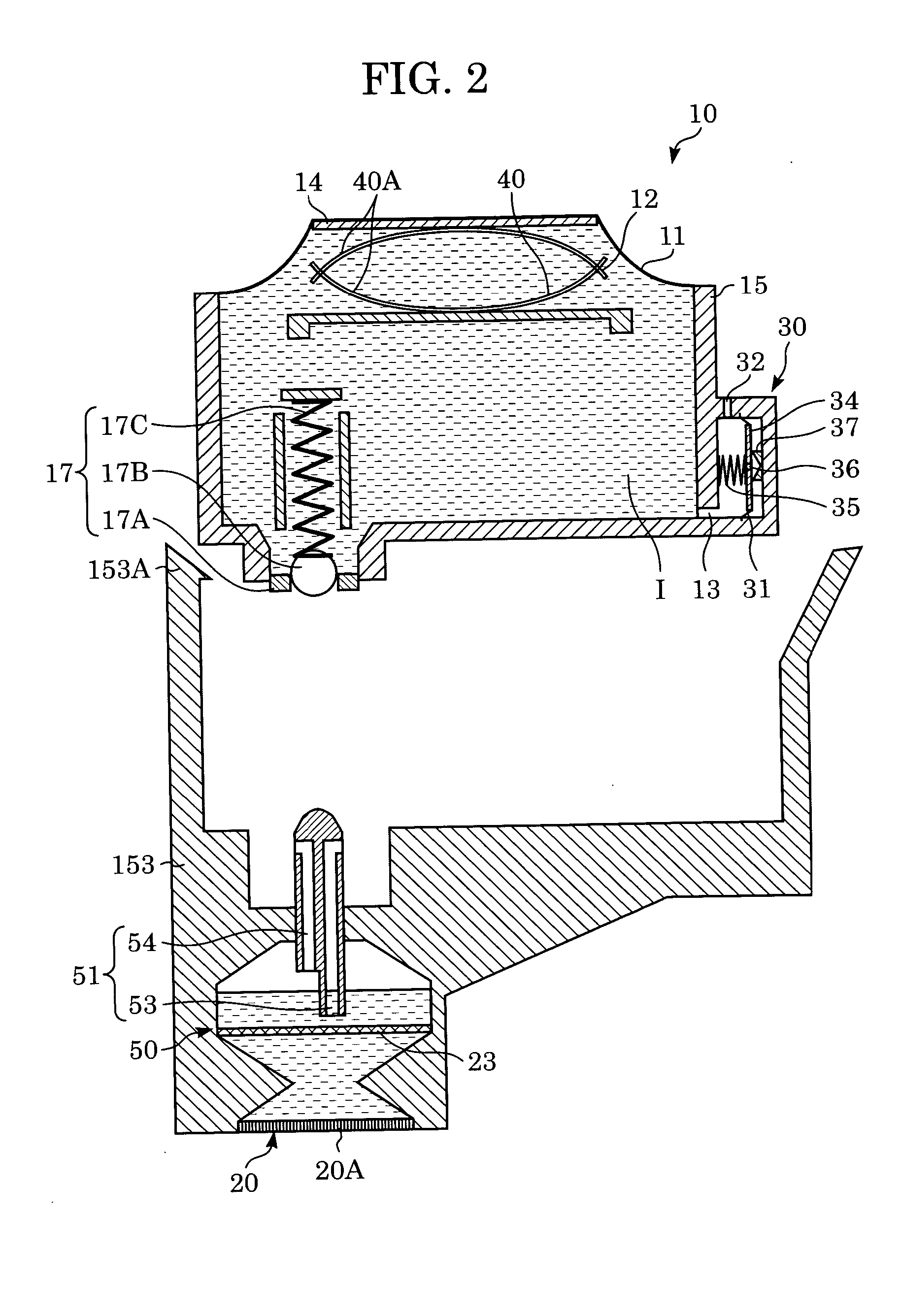
first embodiment
Characteristic Arrangement and Operation of First Embodiment
Accordingly, in the present invention, the multi-meniscus state particularly in the air flow path is eliminated and the basic gas / liquid exchange operation is securely executed so that built-up air can be smoothly and promptly transferred. For this purpose, in the first embodiment, the heights of the tank side openings of both the flow paths are also provided with a difference of heights in the vertical direction.
A process for eliminating bubbles to the ink tank of the embodiment arranged as shown in FIG. 1 will be explained in detail using FIGS. 7 to 12.
First, FIG. 7 shows a state that the ink in the ink tank 10 has been completely consumed. At the time, although the deformation of the spring member 40 is maximized, the air pressure in the ink tank 10 is managed to a pressure lower than an atmospheric pressure by a pressure determined by the spring member 35 and the pressure plate 34 in the valve chamber 30 by the act...
embodiment
Arrangement Applicable to Embodiment
Next, an ink tank replacement state for causing the arrangement of the above embodiment to more effectively function will be explained.
FIG. 14 shows a state just after the ink in the ink tank 10 has been almost completely consumed. In this state, the ink flow path 53 is filled with ink. However, since the tank side opening position of the air flow path 54 is located at a relatively upper position, the air flow path 54 is in the multi-meniscus state because air is captured thereinto.
When the ink tank 10 is replaced with a new ink tank 10 in this state, first, ink and gas are transferred from the liquid chamber 50 into the ink accommodation chamber 12 through the air flow path 54 as explained in FIGS. 8 and 9. However, since the position of the ink interface in the liquid chamber 50 is located near to the head side opening of the air flow path 54, the ink in the liquid chamber 50 is also captured into the ink flow path 53 when the ink and the ga...
PUM
 Abstract
Description
Claims
Application Information