Calibration jig for a stereoscopic camera and calibrating method for the camera

a stereoscopic camera and calibration method technology, applied in the field of calibration jigs for stereoscopic cameras and calibrating methods for cameras, can solve the problems of inability to compare a plurality of photographed images with one another, inability to accurately grasp the shape or the like of chips, and difficulty in obtaining an appropriate mounted state, etc., to achieve the effect of accurate grasping the spatial disposition of a subject to be photographed, easy photographing, and best

Inactive Publication Date: 2005-03-31
TDK CORPARATION
View PDF2 Cites 9 Cited by
  • Summary
  • Abstract
  • Description
  • Claims
  • Application Information

AI Technical Summary

Benefits of technology

[0015] According to the present invention, there is found the center of the photographed image of the jig obtained by photographing the jig disposed at the center of the photographing field of view in the plurality of cameras by each camera. When for example, the jig is a sphere, the photographed image thereof obtained by each of the plurality of cameras is a circle and the center thereof always coincides with the center of the jig which is a sphere. Accordingly, by finding the amount of deviation between the center of the circle photographed by each camera and the center of the photographing field of view, it is possible to find the amount of deviation between the center of the photographing field of view of each camera and the spatial center to be photographed by the plurality of cameras. By carrying out the calibration of the positions of the cameras or the photographed image on the basis of this amount of deviation, it becomes possible to accurately grasp the spatial disposition of a subject to be photographed.
[0016] If the shape of the jig is such that the centers of the photographed images thereof obtained by the respective cameras spatially coincide with one another, it is possible to perform each of the above-described operations. Accordingly, in conformity with the camera disposed, for example, a regular polyhedron, a rectangular parallelepiped or the like can be used as the jig. These shapes can be easily made into a construction which has a plurality of planes substantially perpendicular to the photographing optical axes of the plurality of cameras, and in which a perpendicular passing through the center of each of the plurality of planes coincides with the center of gravity, and it is possible to easily make the centers of the plurality of photographed images spatially coincident with one another. Also, it is desirable that these shapes or the like be suitably selected in conformity with the shape, posture, disposition, etc. of a subject actually photographed and recognized by the cameras.
[0017] Also, as a method of fixing the jig, the specific method thereof is not particularly restricted if it is a method which, when the center of the photographed image of the jig is to be found, does not affect the operation. For example, by supporting the jig by a transparent material such as resin, glass or water, it becomes possible to easily photograph only the image of the jig, and the best effect is obtained. Also, a similar effect will be obtained even if for example, the jig is formed of a magnetic material and also, a suitable magnetic force is made to act on the jig, or the floating state of the jig is maintained by a gas. Or use may be made of very thin piano wire or a bar-shaped supporting member, and when the center of the photographed image is to be found, the supporting member may be made to act on a position having no influence, for example, in a case where the jig is a regular polyhedron, a surface on which the cameras are not disposed.
[0018] The jig according to the present invention constructed above is simple in its construction and can also be constructed with the size, weight, etc. thereof suppressed. Accordingly, it is easy to add this jig to an existing inspecting apparatus or the like, and there can be obtained the effect that the calibrating accuracy of the individual cameras, and particularly the camera for photographing a subject from sideways or the like, can be markedly improved.
[0019] According to the present invention, for the cameras disposed correspondingly to individual directions to photograph a subject from a plurality of directions, a single jig is photographed, whereby it becomes possible to easily and simply calibrate the disposition or the photographing positions of the individual cameras. The jig used in the present invention is simple in its construction and therefore, it is also easy to add it to an inspecting apparatus or the like for effecting the confirmation of the position of a subject by the use of a plurality of cameras.

Problems solved by technology

At that time, unless the positional relation between the photographing centers or the like of the individual cameras is grasped in advance, it becomes impossible to compare a plurality of photographed images with one another.
Therefore, it becomes necessary to grasp and avoid, for example, the surrounding chips or the bumps thereof, or the vertices or the like of the unevenness of bumps on the circuit boards, and there is conceivable a case when it becomes difficult to obtain an appropriate mounted state by the positioning hitherto used.
In this case, it is impossible to accurately grasp the shape or the like of the chips by only the cameras comprising a conventional construction and installed in the same or opposed directions.

Method used


Image

  • Calibration jig for a stereoscopic camera and calibrating method for the camera
  • Calibration jig for a stereoscopic camera and calibrating method for the camera
  • Calibration jig for a stereoscopic camera and calibrating method for the camera

Examples


first embodiment

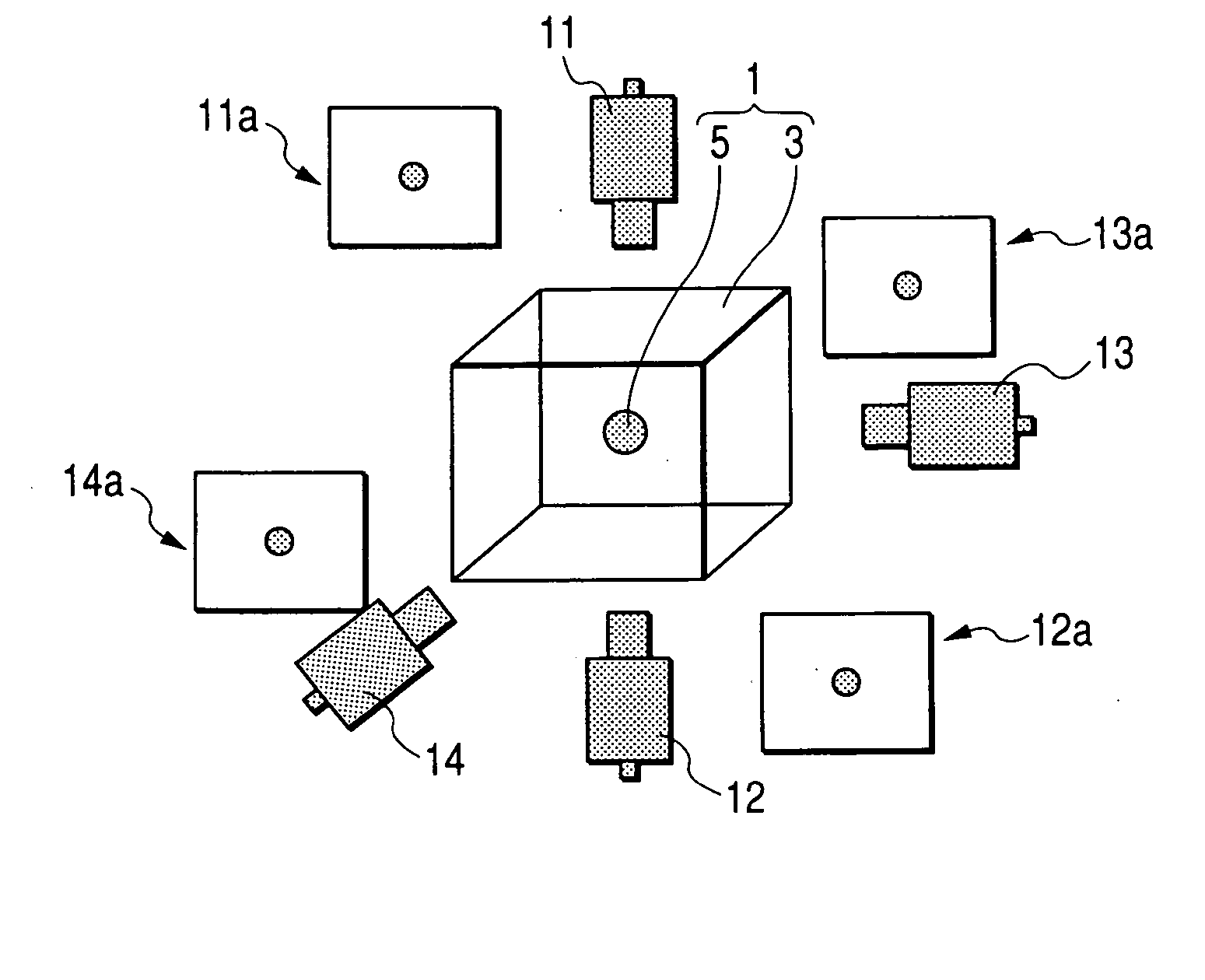
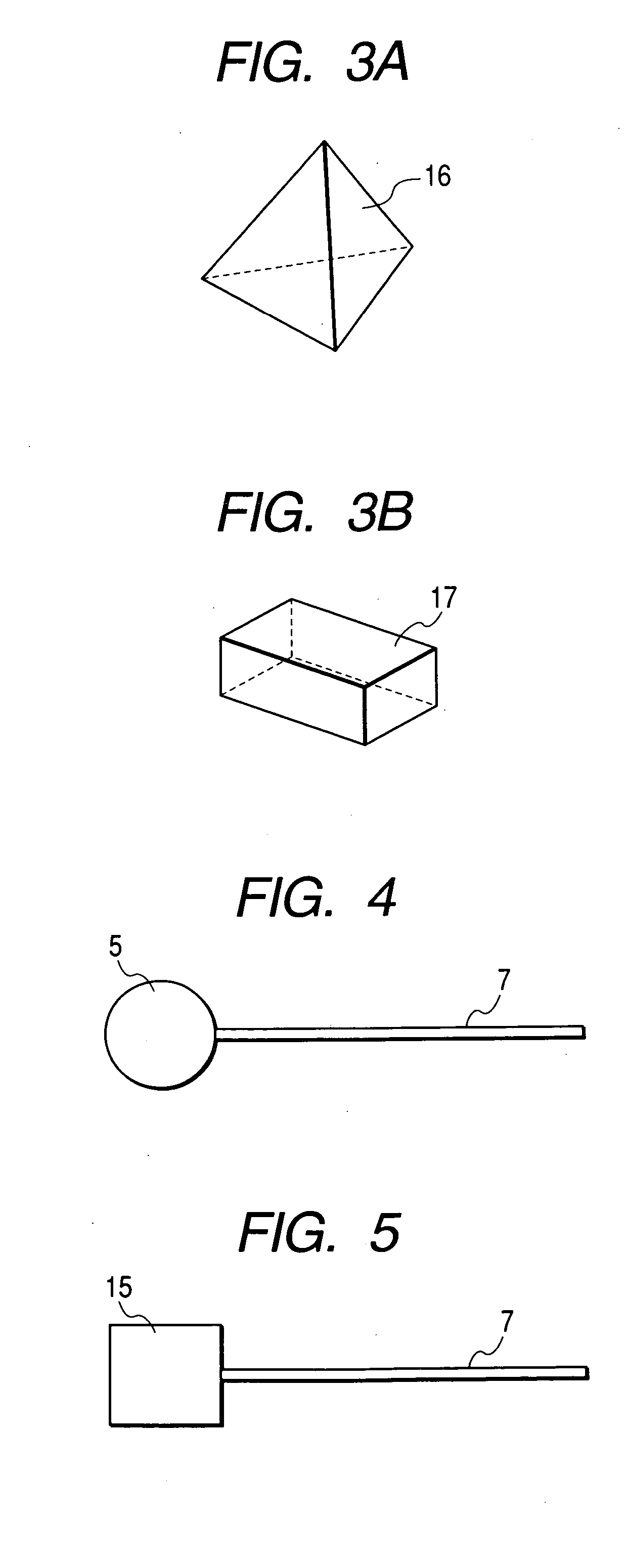
[0026]FIG. 1 schematically shows a jig according to a first embodiment of the present invention, and a case where the position calibration of a plurality of (in this case, four) cameras is effected by the use thereof. In the present embodiment, there are shown the essential portions of a calibrating method in a photographing system for photographing a subject from above, below, the front of and the side of it. This photographing system is comprised of an upper camera 11, a lower camera 12, a front camera 13 and a side camera 14. The jig 1 according to the present embodiment is comprised of a true sphere 5 which is the center of the jig formed, for example, of iron which is low in the transmittance for light, and a transparent acryl resin portion 3 for fixing and supporting it substantially at the center, and is installed at a position which is substantially the center of each of the photographing fields of view of these cameras.

[0027] When the jig is photographed by the individual ...

second embodiment

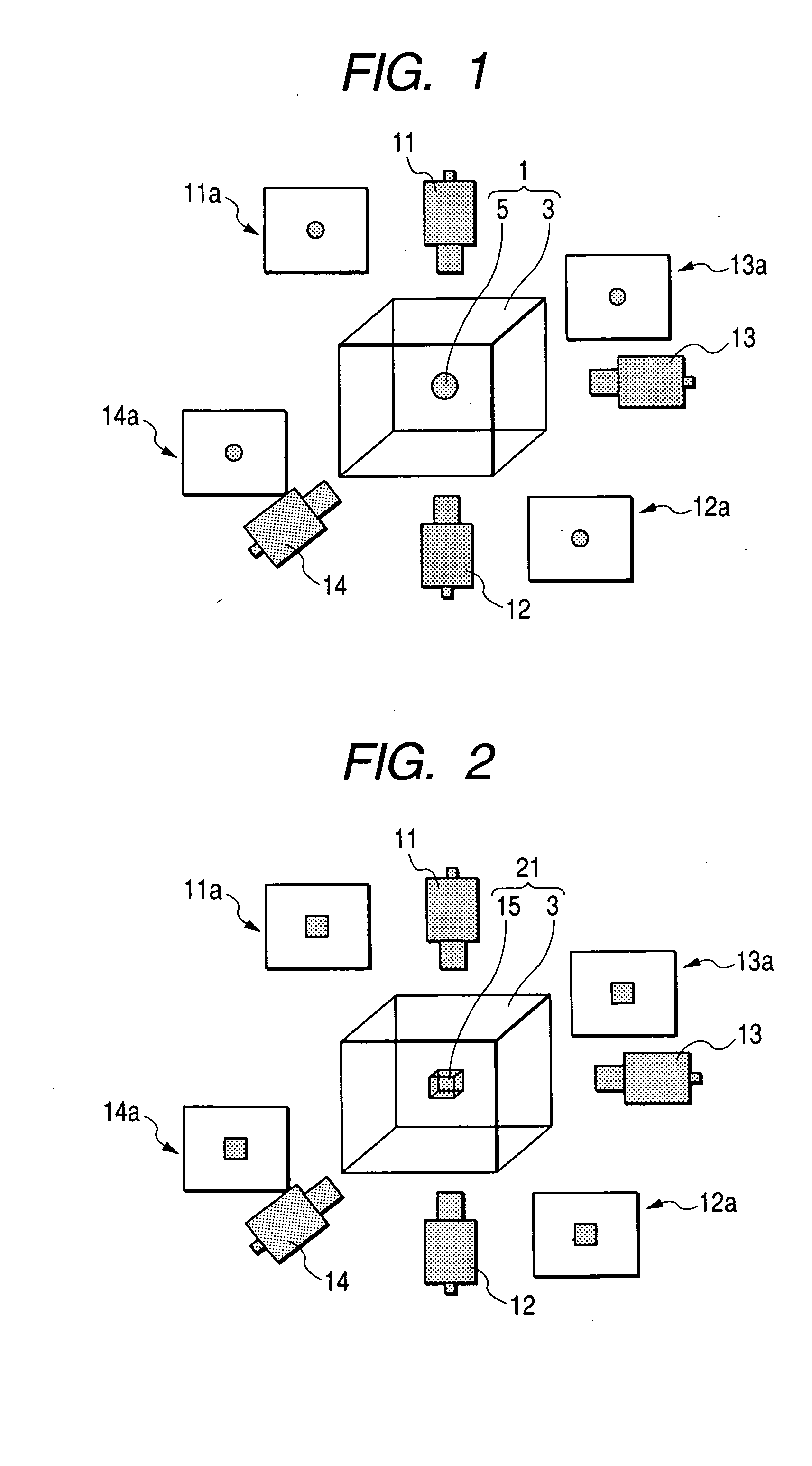
[0029]FIG. 2 shows a jig according to a second embodiment of the present invention, and a case where the position calibration of a plurality of (in this case, four) cameras is effected by the use thereof. A camera system in the present embodiment is the same as that described in the first embodiment and therefore, the portions thereof are given the same reference characters as those in FIG. 1 and need not be described here. In the present embodiment, use is made of a jig 21 in which the true sphere 5 which is the center of the jig in FIG. 1 is replaced by a regular hexahedron (a cube) 15. The regular hexahedron 15, when disposed so that the individual surfaces thereof may be substantially perpendicular to the photographing optical axes of a plurality of cameras, easily makes a perpendicular passing through the center of each of a plurality of planes coincident with the center of gravity, and it is possible to easily make the centers of a plurality of photographed images spatially co...


PUM


Abstract

The present invention has as its object the provision of a jig for carrying out, in a position recognizing a subject having cameras for photographing a subject from a plurality of directions, the position calibration or the like of these cameras. The jig is disposed as a jig for calibration near the photographing center in the plurality of cameras, and is comprised of a portion for fixing and supporting, for example, a true sphere in which the centers found from photographed images obtained by the cameras for photographing the jig spatially coincide with one another.

Description

BACKGROUND OF THE INVENTION [0001] 1. Field of the Invention [0002] This invention relates to a jig used to calibrate, for a so-called stereoscopic camera, i.e., cameras disposed correspondingly to individual directions to photograph a subject from a plurality of directions, the photographing positions of these individual cameras, and a calibrating method for these cameras. [0003] 2. Related Background Art [0004] For example, in the process of mounting a chip-shaped electronic part on a circuit board, in order to recognize the held positions of the electronic part and the circuit board, respective ones of them held at a reference position are photographed by discrete cameras or the like, and the correction of the positional deviation of the individual ones is effected from the comparison between the respective photographed images. At that time, unless the positional relation between the photographing centers or the like of the individual cameras is grasped in advance, it becomes imp...

Claims


Application Information

Patent Timeline
Patent Type & Authority Applications(United States)
IPC IPC(8): G01C11/06G01B11/00G03B15/00G03B35/00H04N13/00H04N17/00
CPCH04N13/0246H04N13/246
Inventor KANEKO, MASAAKIHAYAMI, KENICHI
Owner TDK CORPARATION
Why Eureka
Try Eureka