Method for providing a self-pinned differential GMR sensor and self-pinned differential GMR sensor

a technology of differential gmr and self-pinned gmr, which is applied in the field of self-pinned differential gmr sensor, can solve the problems of contamination, the sv sensor's response to an external application change, and the pinned layer's magnetization will no longer be pinned in the desired direction

Inactive Publication Date: 2005-03-31
HITACHI GLOBAL STORAGE TECH NETHERLANDS BV
View PDF11 Cites 77 Cited by
  • Summary
  • Abstract
  • Description
  • Claims
  • Application Information

AI Technical Summary

Benefits of technology

[0018] The present invention solves the above-described problems by providing a differential GMR head that eliminates the need for antiferromagnetic (AFM) pinning layers.

Problems solved by technology

For example, while the head is flying over the disk surface, it may hit a particle (contamination).
If any of these thermal effects cause the SV sensor to exceed the antiferromagnet's blocking temperature the magnetization of the pinned layer will no longer be pinned in the desired direction.
This will lead to a change in the SV sensor's response to an externally applied magnetic field, and thus to errors in data read back from the disk.

Method used


Image

  • Method for providing a self-pinned differential GMR sensor and self-pinned differential GMR sensor
  • Method for providing a self-pinned differential GMR sensor and self-pinned differential GMR sensor
  • Method for providing a self-pinned differential GMR sensor and self-pinned differential GMR sensor

Examples


Embodiment Construction

[0035] In the following description of the embodiments, reference is made to the accompanying drawings that form a part hereof, and in which is shown by way of illustration the specific embodiments in which the invention may be practiced. It is to be understood that other embodiments may be utilized because structural changes may be made without departing from the scope of the present invention.

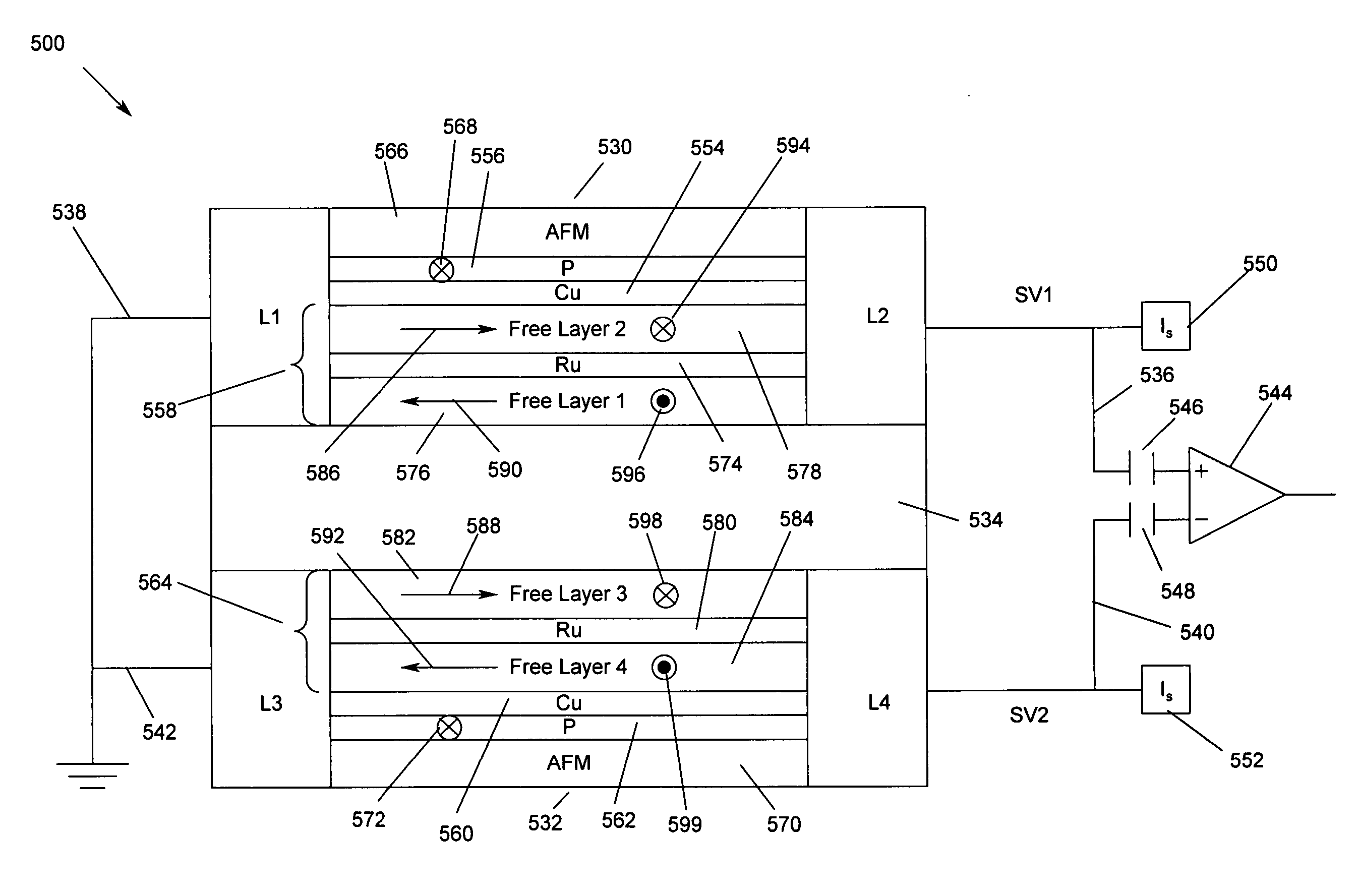
[0036] The present invention provides a method for providing a self-pinned differential GMR sensor and self-pinned differential GMR sensor. The structure of the differential GMR head eliminates the need for antiferromagnetic (AFM) pinning layers.

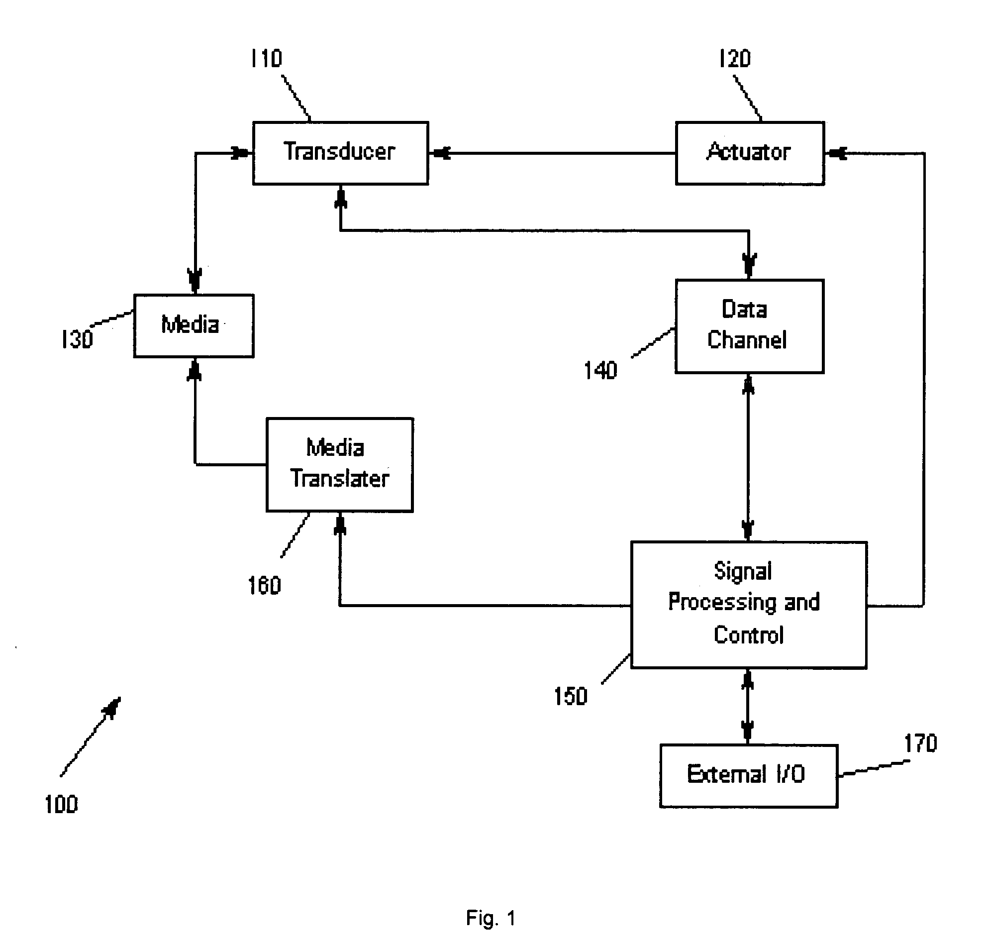
[0037]FIG. 1 illustrates an exemplary storage system 100 according to the present invention. A transducer 110 is under control of an actuator 120, whereby the actuator 120 controls the position of the transducer 110. The transducer 110 writes and reads data on magnetic media 130. The read / write signals are passed to a data channel 140. A signal proc...


PUM

PropertyMeasurementUnit
magnetizationsaaaaaaaaaa
gap lengthaaaaaaaaaa
ferromagneticaaaaaaaaaa

Abstract

A method for providing a self-pinned differential GMR sensor and self-pinned differential GMR sensor. The differential GMR head includes two self-pinned GMR sensors separated by a gap layer. The gap layer may act as a bias structure to provide antiparallel magnetizations for the first and second free layers without using an antiferromagnetic layer. The gap layer may include four NiFe ferromagnetic layers separated with three interlayers. The gap may also be formed to include a structure defined by Ta/Al2O3/NiFeCr/CuOx. One of the pinned layer may include three ferromagnetic layers so that the top ferromagnetic layer of the bottom pinned layer and the bottom ferromagnetic layer of the bottom pinned layer have a magnetization 180° out of phase. The self-pinned GMR sensors may include synthetic free layers that includes a first free sublayer, an interlayer and a second free sublayer that are biased 180° out of phase.

Description

BACKGROUND OF THE INVENTION [0001] 1. Field of the Invention [0002] This invention relates in general to sensors for magnetic storage devices, and more particularly to a method for providing a self-pinned differential GMR sensor and self-pinned differential GMR sensor. [0003] 2. Description of Related Art [0004] Magnetic recording is a key segment of the information-processing industry. While the basic principles are one hundred years old for early tape devices, and over forty years old for magnetic hard disk drives, an influx of technical innovations continues to extend the storage capacity and performance of magnetic recording products. For hard disk drives, the areal density or density of written data bits on the magnetic medium has increased by a factor of more than two million since the first disk drive was used for data storage. Areal density continues to grow due to improvements in magnet recording heads, media, drive electronics, and mechanics. [0005] Magnetic recording head...

Claims


Application Information

Patent Timeline
Patent Type & Authority Applications(United States)
IPC IPC(8): G11B5/127G11B5/33G11B5/39
CPCB82Y10/00B82Y25/00G11B2005/3996G11B5/3932G11B5/3912
Inventor GILL, HARDAYAL SINGH
Owner HITACHI GLOBAL STORAGE TECH NETHERLANDS BV
Why Eureka
Try Eureka