Led and led lamp

a technology of led lamps and diodes, which is applied in the direction of lighting, light source combinations, instruments, etc., can solve the problems of long life of led lamps, high power, and difficult manufacturing of led lamps, and achieve the effects of rapid increase of chip temperature, rapid decrease of led luminous efficiency, and high power

Inactive Publication Date: 2005-03-31
LOU MANE
View PDF14 Cites 247 Cited by
  • Summary
  • Abstract
  • Description
  • Claims
  • Application Information

AI Technical Summary

Benefits of technology

[0005] The object of the invention is to overcome the disadvantages of great heat resistance between the LED and the heat sink, the rapid increase of the chip temperature and thereby the rapid decrease of the LED luminous efficiency; to overcome the disadvantages of glue split between the metal base and the circuit board after a long operating time due to the different heat expansion coefficient between them, the great heat resistance increase between LED and the heat sink and thereby the LED damage by overheating; so that a high power, high efficiency and long lifetime LED and LED lamp can be provided.
[0022] A traffic lamp consisted of the above LED is characterized in that the LED has a divergence angle between 3° and 60°, and is mounted on a heat sink near the focus of the parabolic reflector of the traffic lamp. The light from some of the LEDs is emitted outside of the window of the original traffic lamp and the remaiding light is radiated outside after reflecting form the parobalical light reflector of the original traffic lamp to obtain the light radiation with desired focus and uniform distribution.
[0026] (1) The heat sink is connected directly and closely to the base so that the heat resistance between the chip and the heat sink is nearly zero, and leading to the efficient escape of the heat created by the LED. In addition, the metal base is connected to the heat sink by metal screws and therefore the heat connection between them is reliable and unchangeable after a long time operation. Therefore, a high power, high efficiency and long lifetime LED can be fabricated;
[0027] (2) The circuit board is disposed on or around the metal base to facilitate the connection between chips and to facilitate dense installation, without the increase of the heat resistance between the chip and the sink.

Problems solved by technology

Glue split increases RE, and results in LED damage by overheating.
In summary, high power, high luminous efficiency and long lifetime LED for lighting is difficult for manufacturing by the prior art.

Method used


Image

  • Led and led lamp
  • Led and led lamp
  • Led and led lamp

Examples


embodiment 1

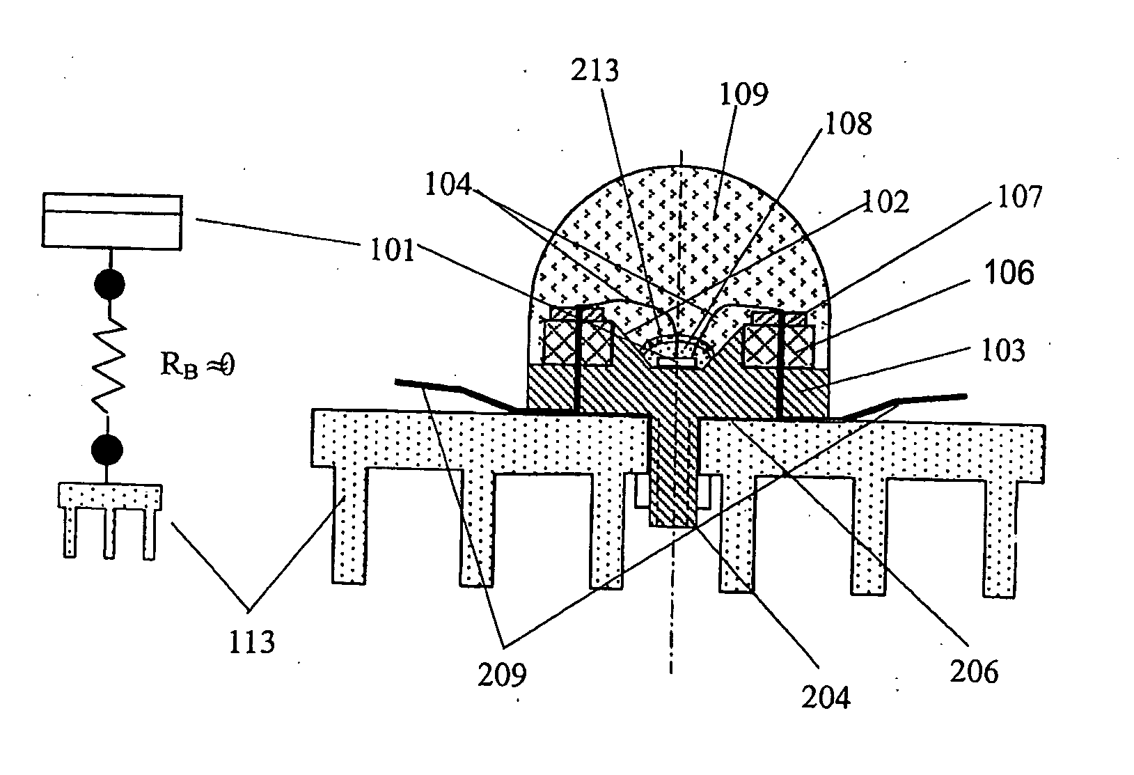
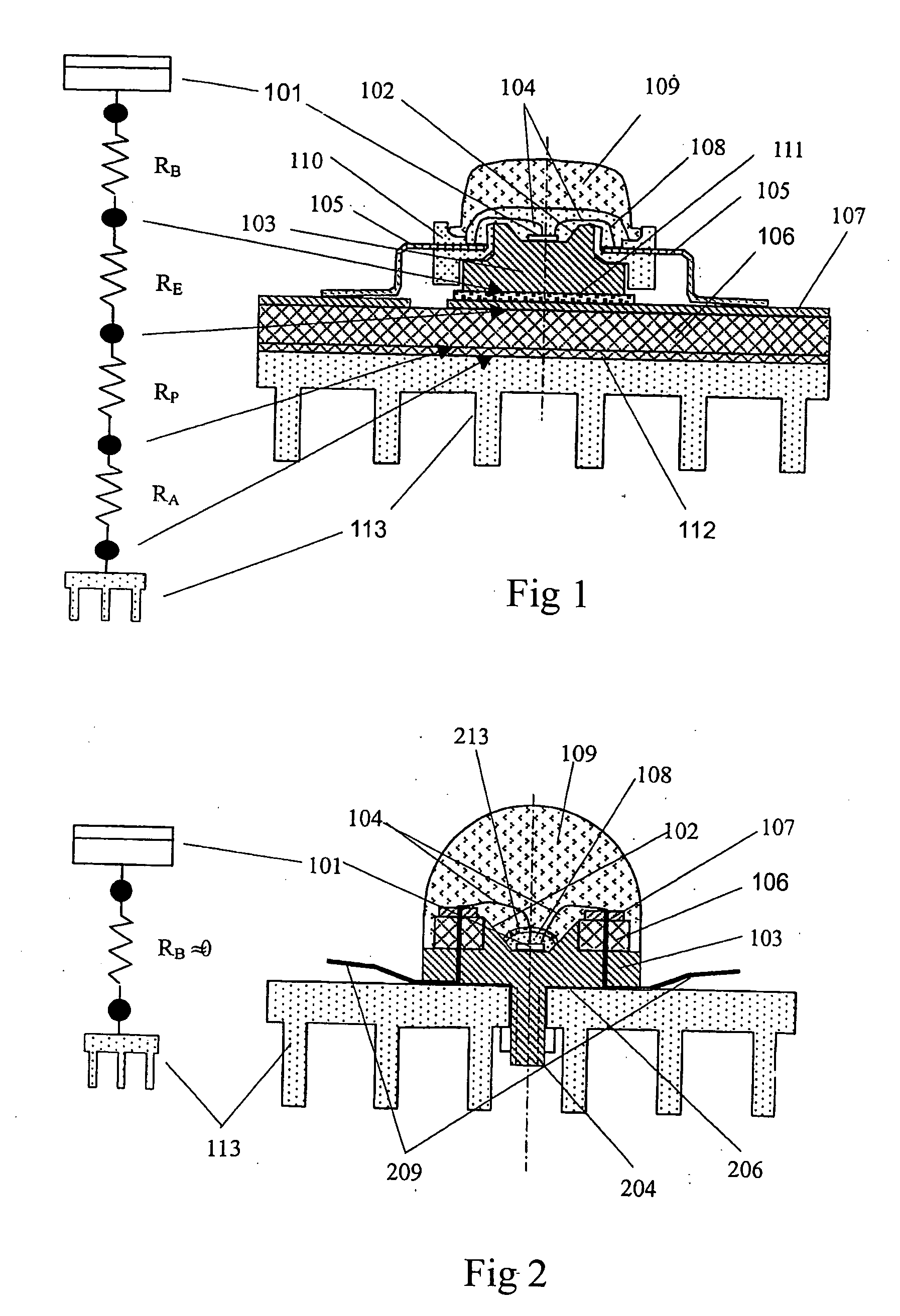
[0042] A LED of the invention, as shown in FIG. 2, is fabricated, in which at least one LED chip 101, such as yellow color light emitting LED, is mounted on the reflective surface of a metal base 103. When more than two LED chips 101 are used, the LED chips may emit the same color light or different color light. The metal base 103 is thermodynamically and mechanically connected to a heat sink 113 closely through at least one screw 204. Heat conduction glue 206 is provided between metal base 103 and the heat sink 113 to obtain better heat connection. A circuit board 106 is disposed on the metal base 103 and has an electrical conductive lager 107, to which outgoing leads 209 are connected. The outgoing leads 209 are insulated from the metal base and the heat sink 113, and are connected to an applied power supply. The LED chip 101 is connected to the circuit board 106 through leads 104. Optical glue 108 and lens 109 are provided on the LED chip 101, light conversion material 213 is pro...

embodiment 2

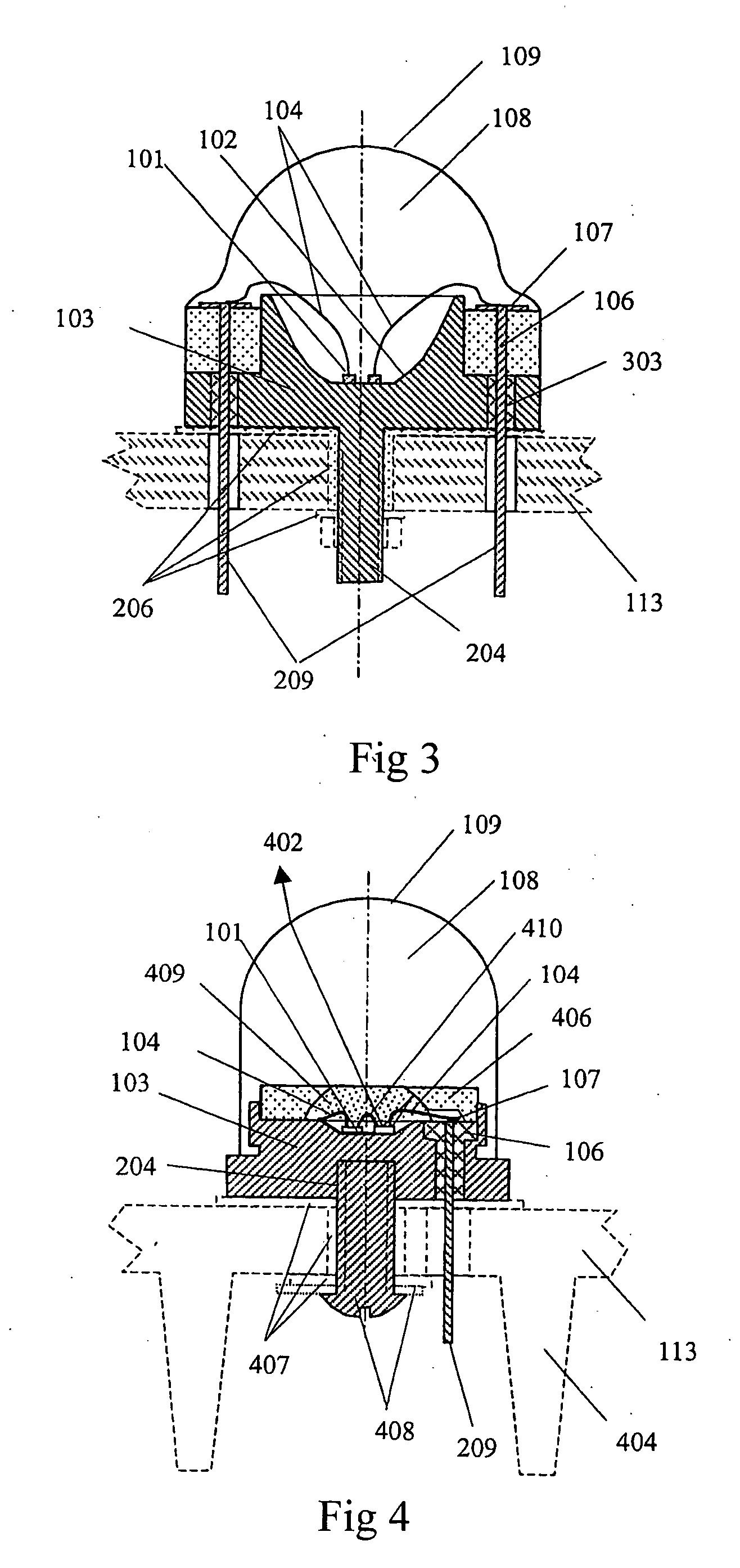
[0043] A LED of the invention is fabricated, in which lower leads are used, as shown in FIG. 3. At least one LED chip 101, for example two LED chips, are mounted on the light reflective surface 102 of the metal base 103. The LED chips emit different color light. The metal base 103 has at least one screw 204 to thermodynamically and mechanically connect the metal base 103 to the heat sink 113 closely. A circuit board 106 is disposed around the metal base 103 and has an electrical conductive lager 103 on it to connect outgoing leads 209. The outgoing wires extend right down wards though the insulation layer 303 and are connected to an applied power supply. Transparent medium is provided on the LED chip 101 and has a top surface designed to be spherical or ellipsoidal depending on the desired output light distribution. The metal base 103 is made of low heat resistively aluminum or its alloy. The remaining is the same as embodiment 1.

embodiment 3

[0044] A LED of the invention, as shown in FIG. 4, is fabricated, in which a light reflector is provided, wherein, a light reflector is added over at least one LED chip 101 so that the light 402 emitted towards the LED sides may be reflected back to the LED chip 101 or the reflecting surface 102, and than emitted forwards. Therefore, the light availability factor is increased. When more than two LED chips are used and radiate different color light, color mixture may be provided between the reflector 406 and the LED chip 101 to enhance light color mixing effect. One electrode of one LED chip 101 is connected to the metal base 103, and then is led outside through at least one of the screw hole 408 and screw 204. The other electrode lead of the LED chip 101 is connected to the outgoing wire 209 through the lead 104. The outgoing wire 209 extends outside through the insulating layer 303 and then is connected to an applied power supply. A lead 410 is connected between each two adjacent L...


PUM


Abstract

This invention relates to a light emitting diode (LED) and a LED lamp consisted of LEDs. The LED comprises at least one LED chip. The LED is mounted on a high heat conductivity base and is connected to an applied power supply through a circuit board. The LED chip also has a transparent medium layer on it. The base top surface acts as a light reflective surface, or a light reflective surface is provided around the base, the LED comprises a screw extended downwards from the base bottom or a screw hole in the base bottom to connect the LED to a heat sink mechanically. The LED is electrically connected to a driving circuit through its outgoing wires. The driving circuit is in turn electrically connected to an electrical connector through its housing. A LED lamp can be fabricated after the LED is enclosed in a transparent bulb housing. The LED has high efficiency, high power and long lifetime and can be used to fabricate LED traffic lamps, LED plane light sources, etc.

Description

TECHNICAL FIELD [0001] This invention relates to a light emitting diode (LED) and LED lamp, more specifically to a high power, high efficiency and long lifetime LED and LED lamp devices, such as illumination lamp, traffic lamp and information display device etc. BACKGROUND OF THE INVENTION [0002] LED has been widely used in signal indication, large screen display, and has advantages of long lifetime, good color, sturdiness, etc. At the present, only low power LED can be fabricated. The power of typical LED is only 20 mA×4V=80 mW, because the increase of the operating current will cause the rapid increase of the LED chip temperature, and in turn the luminous efficiency will decrease nearly linearly with the chip temperature increase. The efficient escape of the large quantity of heat created by LED has become the key to fabricating LED and LED lamp. [0003] For prior typical high power LED, which is under developing as shown in FIG. 1, a LED chip 101 is bound on the light reflecting s...

Claims


Application Information

Patent Timeline
Patent Type & Authority Applications(United States)
IPC IPC(8): F21V19/00F21K99/00F21S2/00F21S8/04F21V8/00F21V15/01F21V29/00F21V29/505F21Y101/02G08G1/095H01L33/58H01L33/60H01L33/64
CPCF21K9/135F21V29/78F21V7/06F21Y2101/02H01L33/62H01L33/642H01L2224/48247Y10S362/80F21V3/00F21V29/76G02B6/0031G02B6/0073G02B6/0085F21W2111/02F21Y2111/001F21Y2113/005F21V29/505F21V29/75H01L2224/48091H01L2924/00014F21K9/232F21Y2107/00F21Y2113/13F21Y2115/10H01L2224/8592H01L2924/181H01L2924/00012
Inventor GE, SHICHAO
Owner LOU MANE
Why Eureka
Try Eureka