Torque Overlay Device for a Hybrid Drive System, and a Method for Operating Such a Hybrid Drive System

Active Publication Date: 2015-11-26
BAYERISCHE MOTOREN WERKE AG
View PDF6 Cites 5 Cited by
  • Summary
  • Abstract
  • Description
  • Claims
  • Application Information

AI Technical Summary

Benefits of technology

[0026]In many cases, it is advantageous if the at least one clutch is configured with a synchronizer element. Suitable synchronizer elements, such as single-cone to triple-cone synchronizers, are known in the prior art. Synchronizer elements can be used to passively reduce, which is to say without active engine intervention, rotational speed differentials between the shaft and the gear to be shifted in a short period of time sufficiently for the shifting process to be completed, for example by engagement of the dog clutches. Advantageously all clutches are implemented with synchronizer elements.
[0027]In an advantageous refinement of the invention, a fixed gearing element is arranged between the

Problems solved by technology

The electric motor is often operated at a less than optimal operating point.
This results in drawbacks, either in terms of power or from an energy point of view.
Power splitting results in energy losses.
This topology, however, is still not optimal with respect to the tractive force or tractive force development or tractive force continuity, in particular when aggregate power is needed during the respective shifting processes.
In addition, the topology is complex in terms

Method used


Image

  • Torque Overlay Device for a Hybrid Drive System, and a Method for Operating Such a Hybrid Drive System
  • Torque Overlay Device for a Hybrid Drive System, and a Method for Operating Such a Hybrid Drive System
  • Torque Overlay Device for a Hybrid Drive System, and a Method for Operating Such a Hybrid Drive System

Examples


Example

DETAILED DESCRIPTION OF THE DRAWINGS

[0048]Only elements and components that are essential for gaining an understanding of the invention are shown in the figures. The shown exemplary embodiment shall be understood to have a purely instructive nature and is intended to provide a better understanding, without limiting the subject matter of the invention.

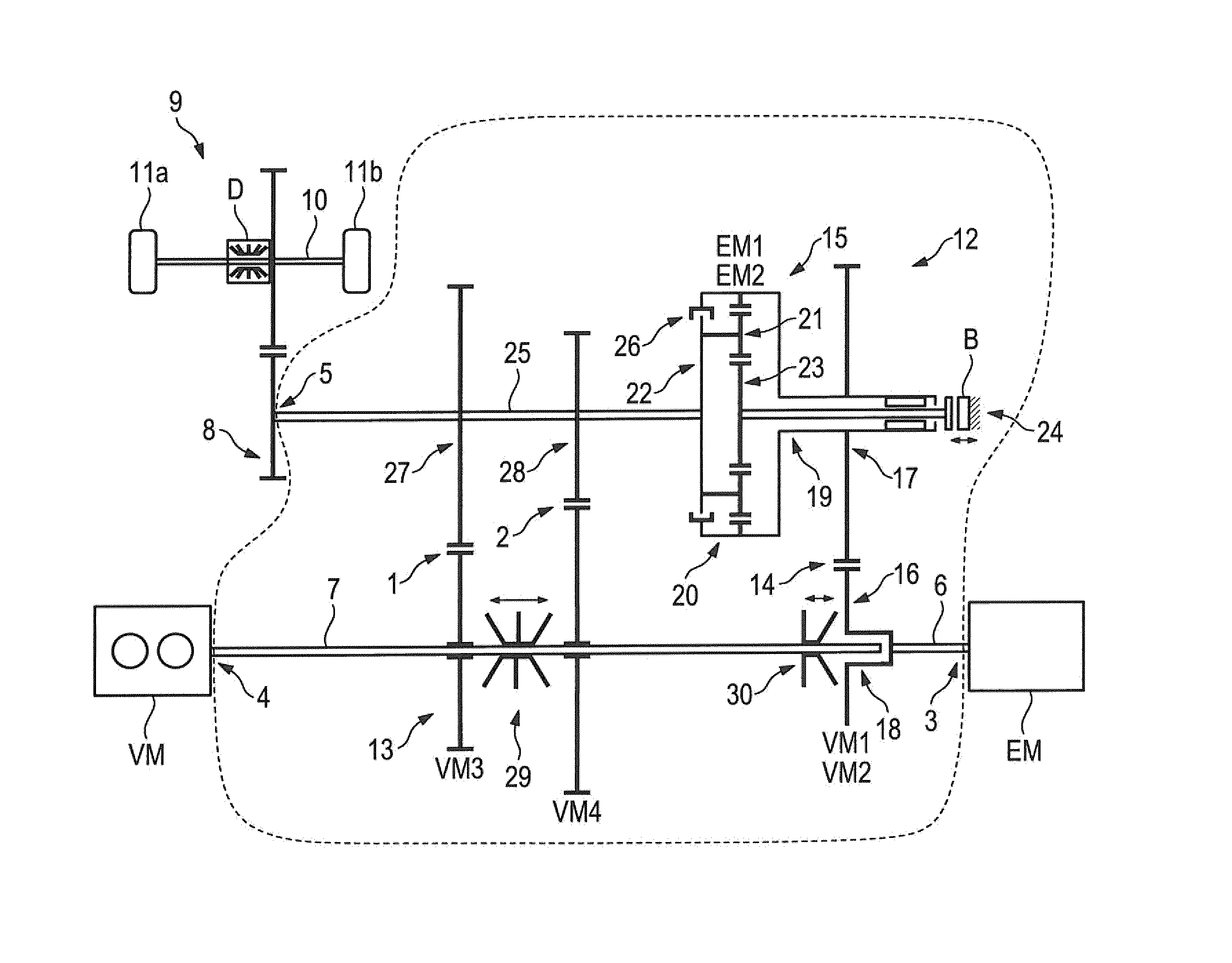
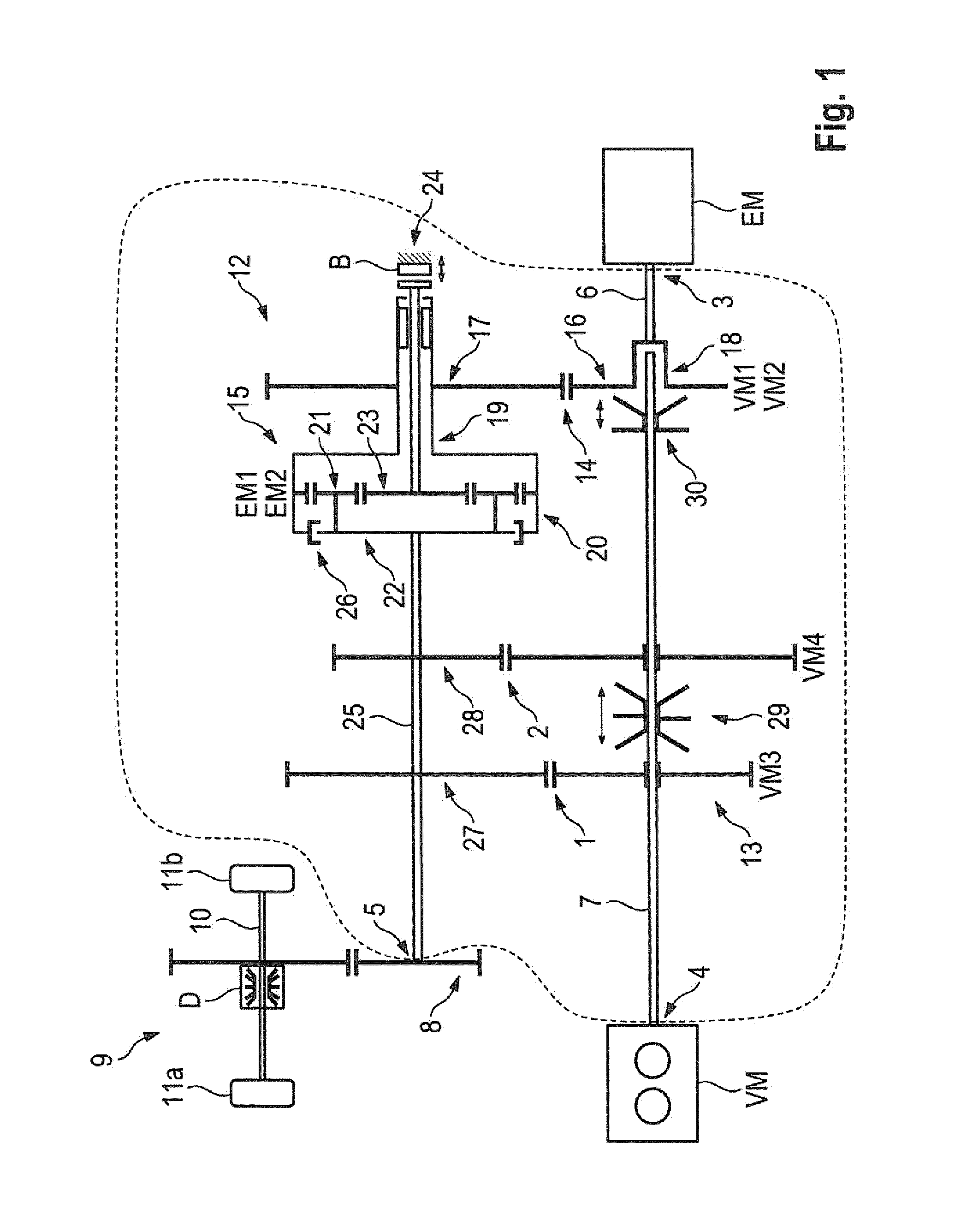
[0049]FIG. 1 shows a hybrid drive 1 implemented according to the invention for use in a passenger motor vehicle. The hybrid drive 1 comprises an internal combustion engine VM, an electric motor EM, and a torque superimposition device implemented according to the invention as a transmission 2. The transmission 2 comprises a first torque input 3 and a second torque input 4, as well as a torque output 5.

[0050]The electric motor EM is coupled to the first torque input 3 in a torque-proof manner, wherein the torque-proof coupling is achieved by means of a first shaft 6 here. For this purpose, the first shaft 6 is coupled to the rotor shaft (...


PUM


Abstract

The invention relates to a torque overlay device for use in a hybrid drive system for motor vehicles having an internal combustion engine, an electric motor and the torque overlay device, wherein a torque of the internal combustion engine and of the electric motor are overlaid using the torque overlay device. The torque overlay device is connected, on the output side, to a driven element of the vehicle, and includes a first and a second torque input and a torque output, as well as a first transmission device and a second transmission device. The electric motor can be coupled to the first torque input in a torque-resistant manner, and the internal combustion engine can be coupled to the second torque input in a torque resistant manner, where the first torque input is connected to the first transmission device and the second torque input is connected to the second transmission device, both in a torque-resistant manner. In addition, the transmission devices may each be coupled, on the driven side, to the torque output of the torque overlay device in a torque-resistant manner.

Description

CROSS REFERENCE TO RELATED APPLICATIONS[0001]This application is a continuation of PCT International Application No. PCT / EP2014 / 051311, filed Jan. 23, 2014, which claims priority under 35 U.S.C. §119 from German Patent Application No. 10 2013 201 946.7, filed Feb. 6, 2013 and 10 2013 211 975.5, filed Jun. 25, 2013, the entire disclosures of which are herein expressly incorporated by reference.BACKGROUND AND SUMMARY OF THE INVENTION[0002]The present invention relates to a torque superimposition device for a hybrid drive and to a method for operating the hybrid drive comprising the torque superimposition device according to the invention. The hybrid drive is particularly suited for use in a passenger motor vehicle.[0003]Numerous hybrid drives are known in the prior art. In most instances, an electric motor is arranged in what is known as a hybrid parallel architecture in such a way that the drive torque of the electric motor can be connected to the output shaft of the internal combust...

Claims


Application Information

Patent Timeline
IPC IPC(8): B60W20/00B60W10/08B60W10/115B60W10/06
CPCB60W20/10B60W10/06B60W10/08B60W2710/105B60W2710/0666B60W2710/083B60W2710/1022B60W10/115B60K6/365B60K6/48B60K6/547F16H2200/2005B60K2006/4816B60W2510/244B60W10/11B60W20/00B60W30/1882B60W10/02B60W2520/10Y02T10/62B60W20/20
Inventor HOESS, BERNHARDHUBER, ROBERTROGGE, SIMONPRIGNITZ, FALK
Owner BAYERISCHE MOTOREN WERKE AG
Why Eureka
Try Eureka