Scalable broadband wireless mesh access network

a wireless mesh access network and wireless mesh technology, applied in the field of wireless networks, can solve the problems of high cost of backhaul services, base stations must be located, and inconvenient operation, and achieve the effect of high data rates

Inactive Publication Date: 2005-03-31
DAVID LADD AS COLLATERAL AGENT +1
View PDF33 Cites 45 Cited by
  • Summary
  • Abstract
  • Description
  • Claims
  • Application Information

AI Technical Summary

Benefits of technology

The invention comprises a mesh access network architecture that provides a combination of high data rates to a large number of users and >99% coverage to potential customers in a service area. The network design also provides scalable capacity that scales to more capacity / users with additional frequency carriers and coverage over a large area with additional base-stations. This is achieved in the presently preferred embodiment of the invention by using a combination of centralized mesh network control and intelligent interference management.

Problems solved by technology

There are a number of issues concerning the design of a wireless network which do not arise in a wired system.
One major drawback of P-MP is that base stations have to be located where it is possible to site a base station.
Base stations are also expensive, and the cost of backhaul services can be prohibitive.
Another major drawback to P-MP is that the cost of the CPE installations, i.e. the “truck roll,” becomes prohibitive in the aggregate as more and more customers are added to the system.
Yet another drawback to P-MP is that there are inevitably be dead zones where some potential customers do not have line of sight (LOS) to the base station, and therefore cannot receive service.
Unfortunately, mesh networking, as currently implemented, does not scale well beyond perhaps five relay nodes.
Latency, i.e. the amount of delay added at each node, is increasingly noticeable as more relaying is necessary to get packets from a customer to the backhaul connection.
One solution to the latency issue is have multiple backhaul connections, but doing so somewhat defeats the cost-effectiveness of mesh networking.

Method used


Image

  • Scalable broadband wireless mesh access network
  • Scalable broadband wireless mesh access network
  • Scalable broadband wireless mesh access network

Examples


example 1

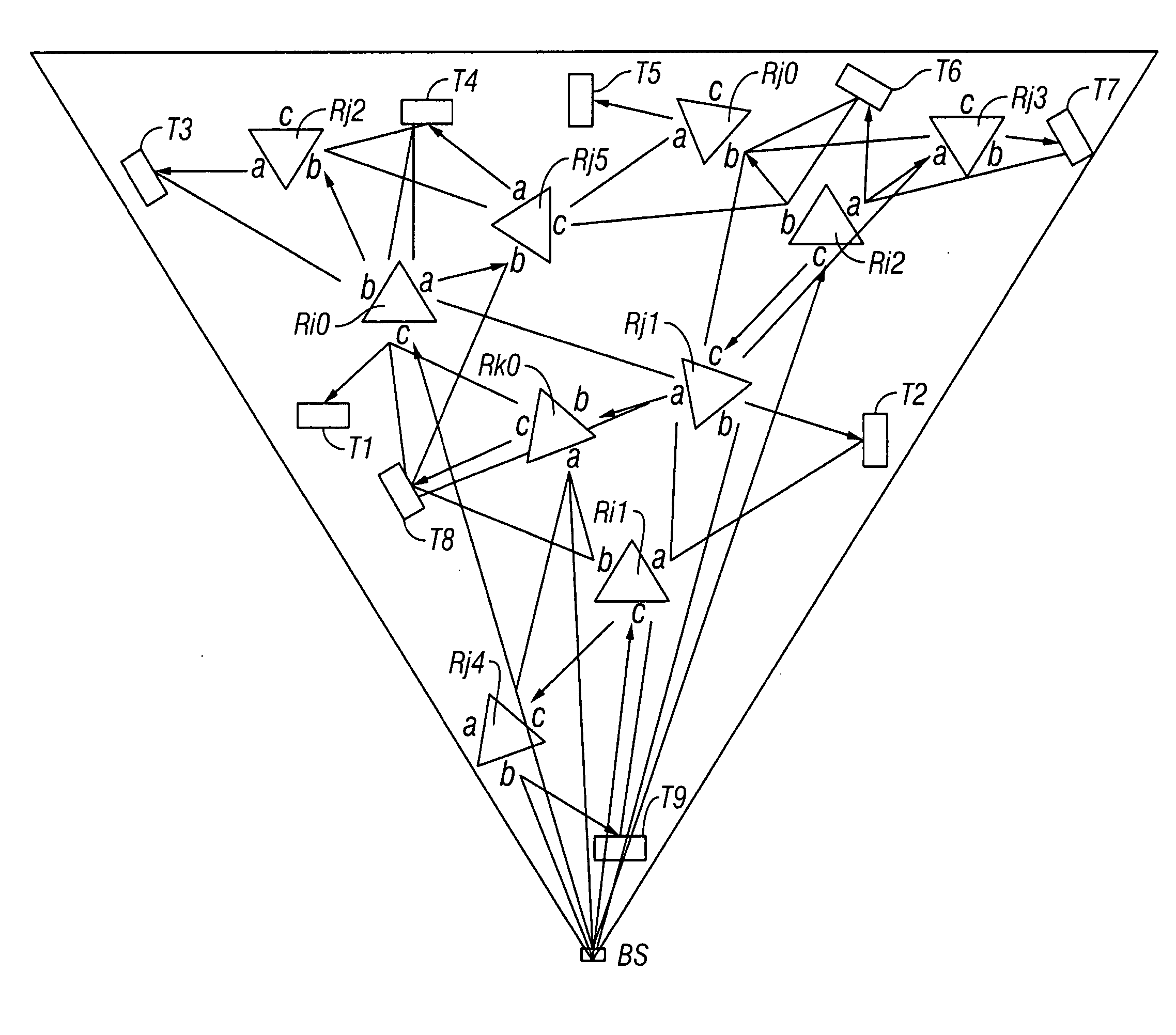
FIG. 1 is a tree diagram that shows a network having eleven nodes and twenty directional links: {I0,1, I1,0, I0,2, I2,0, I1,3, I3,1, I1,4, I4,1, I2,5, I5,2, I2,6, I6,2, I2,7, I7,2, I4,8, I8,4, I5,9, I95, I6,10, I10,6}

Suppose that the set of links L0,1 that gets interference, i.e. that cannot be active while link I0,1 is active, is: L0,1={I1,0, I0,2, I2,0, I1,3, I3,1, I1,4, I4,1, I5,9, I8,4}

Similarly, suppose there are the following interference sets: L1,0={I0,1, I0,2, I2,0, I1,3, I3,1, I1,4, I4,1, I9,5, I4,8} L0,2={I1,0, I0,1, I2,0, I2,5, I5,2, I2,6, I6,2, I2,7, I7,2, I6,10} L2,0={I1,0, I0,1, I0,2, I2,5, I5,2, I2,6, I6,2, I2,7, I7,2, I10,6} L1,3={I1,3, I1,4, I4,1, I0,1, I1,0} L3,1={I1,3, I1,4, I4,1, I0,1, I1,0} L1,4={I1,4, I1,3, I3,1, I1,0, I0,1, I4,8, I8,4, I2,5, I7,2} L4,1={I1,4, I1,3, I3,1, I1,0, I0,1, I4,8, I8,4, I5,2, I2,7} L2,5={I5,2, I0,2, I2,0, I2,6, I6,2, I2,7, I7,2, I5,9, I9,5, I1,4} L5,2={I2,5, I0,2, I2,0, I2,6, I6,2, I2,7, I7,2, I5,9, I9,5, I4,1} L2,6={I6,2, I0,2, I...

example 2

Continuing with Example 1 above, the following is one possible schedule for links requesting bandwidth: S={({I5,9, I6,10, I3,1}, 10), ({I0,2}, 35), ({I2,6, I0,1}, 5), ({I2,6, I1,0}, 10), ({I2,5}, 20)}

This schedule uses 10+35+5+10+20=80 credits to satisfy 35+20+15+10+10+10+10+5=115 requested credits. The average activity concurrency is 115 / 80=1.4375.

This schedule is not necessarily the best schedule for this example. In fact, using the algorithm described in detail below, one can find a better schedule using less credits while still satisfying all bandwidth requests.

An optimal schedule must satisfy the following conditions:

For any link, granted credits equals requested credits Σljk⊂Li Gi=Rjk

Minimal total network resource spent (ΣGi)<=(ΣG′i) for ∀S′={(L′i, G′i)}

Because this problem is NP-hard, a heuristic algorithm is disclosed herein for a near optimal solution. For purposes of the discussion herein, a problem is NP-hard if an algorithm for solving it can be transla...

example 3

Use this algorithm to compute the schedule for Example 2.

Step 1 (see Table 2 below).

TABLE 2Step 1Degree of interferenceLinkα(Iij, L)Requested credit Rijα(Iij, L) * RijI0,2535175I2,532060I2,631545I1,031030I5,921020I6,1021020I3,121020I0,14520

Steps 2-5:

Get the first Schedule S={({I0,2, I5,9, I3,1}, 10)}.

Go back to step 1 (see Table 3 below).

TABLE 3Go Back to Step 1Degree of interferenceLinkα(Iij, L)Requested credit Rijα(Iij, L) * RijI0,2525125I2,522040I2,621530I1,021020I6,1021020I0,12510

Steps 2-5:

Get a revised Schedule S={({I0,2, I5,9, I3,1}, 10), ({I0,2}, 25)}.

Go back to step 1 (see Table 4 below).

TABLE 4Go Back to Step 1Degree of interferenceLinkα(Iij, L)Requested credit Rijα(Iij, L) * RijI2,512020I2,611515I1,011010I6,1011010I0,1155

Steps 2-5:

Get a revised Schedule: S={({I0,2, I5,9, I3,1}, 10), ({I0,2}, 25), ({I2,5, I1,0, I6,0}, 10)}.

Go back to step 1 (see Table 5 below).

TABLE 5Go Back to Step 1Degree of interferenceLinkα(Iij, L)Requested credit Rijα(Iij, L)...


PUM


Abstract

The invention comprises a mesh access network architecture that provides a combination of high data rates to a large number of users and >99% coverage to potential customers in a service area. The network design also provides scalable capacity that scales to more capacity/users with additional frequency carriers and coverage over a large area with additional base-stations. This is achieved using a combination of centralized mesh network control and intelligent interference management.

Description

BACKGROUND OF THE INVENTION 1. Technical Field The invention relates to wireless networks. More particularly, the invention relates to the overall network architecture of a scalable broadband wireless mesh access network. 2. Description of the Prior Art There are a number of issues concerning the design of a wireless network which do not arise in a wired system. Two known approaches to wireless networking are those of point-multipoint networking and mesh networking. Point-Multipoint (P-MP) P-MP systems are by far the most common network architecture used in broadband wireless Internet access. A base station is established in a location visible to a number of customers. A backhaul connection is established to the base station, via wireless or wireline, and customer premise equipment (CPE) is installed at each customer's location. It is usually necessary to use an outdoor antenna to achieve reasonable range and performance. One major drawback of P-MP is that base stations have ...

Claims


Application Information

Patent Timeline
Patent Type & Authority Applications(United States)
IPC IPC(8): H04L12/28H04L12/56
CPCH04W16/02H04W88/08H04W84/02H04W16/14
Inventor RATH, KAMLESH
Owner DAVID LADD AS COLLATERAL AGENT
Why Eureka
Try Eureka