Unless some type of positional compensation is provided, temperature changes that occur during equipment warm-up or during extended operation can cause shifting of a color separator prism, or of similar components, with respect to an intended
optical path.
In apparatus using a high-energy illumination source, for example, heat generated from the illumination source and from other equipment sources can cause ambient and
chassis temperatures to change over time.
Due to mechanical
hysteresis effects, transitions in temperature can cause undesirable repositioning of mounted components during temperature transitions or excursions.
Because of this, even where careful warm-up procedures are followed for achieving suitable
operating temperature for an optical subsystem, some shifting or slippage of a prism or lens
mount can occur.
This results in undesirable shifting of the paths of modulated light, possibly requiring constant recalibration and readjustment in order to maintain pixel-to-pixel registration between color paths.
Conventional prism mounting techniques for color separator prisms and other
heat sensitive prism applications are characterized by mechanical complexity, over-constraint,
crowding, and need for precision adjustment and liberal allowed tolerances for heat effects.
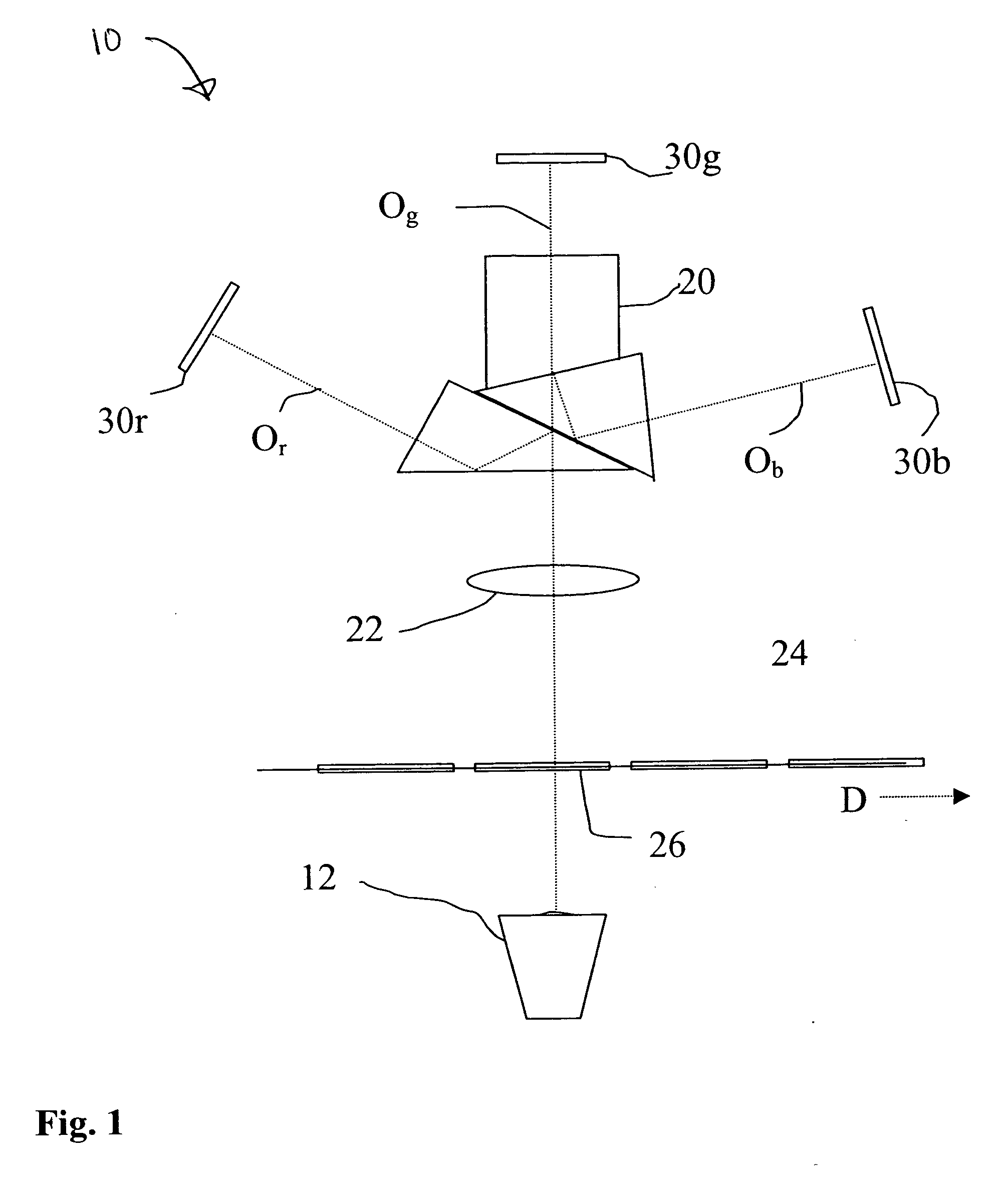
However, attempts to provide suitable prism mounting using spring forces, frames, or other kinematic mechanical constraints have proved inadequate to the task of providing a stable mount for many types of color separator prism 20 in
telecine apparatus 10, primarily due to sliding friction at kinematic contact points, caused by
thermal expansion of dissimilar materials at different rates.
The crux of the problem is that once the proper
operating temperature is reached, optical components may not return to a precise position, due to some degree of temperature-related mechanical
hysteresis.
This sliding friction can occur even when kinematic mounting techniques are employed.
As a result, pixel-to-pixel registration between the color optical axes can be shifted, causing undesirable color fringing in printed frames 26.
Conventional mounting and fastening techniques for color separator prism 20 have yielded poor results due to temperature-related mechanical
hysteresis with
telecine apparatus 10.
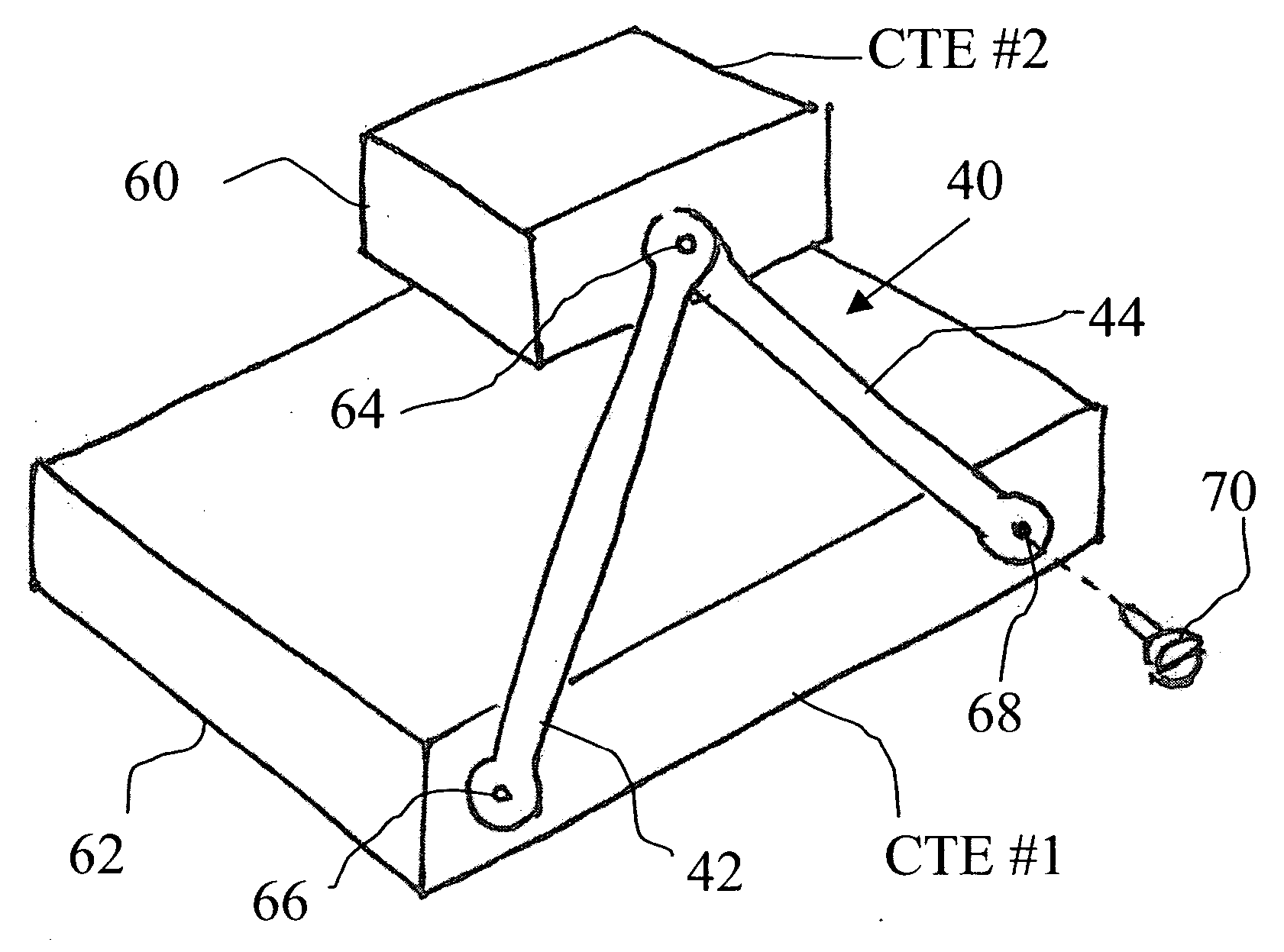
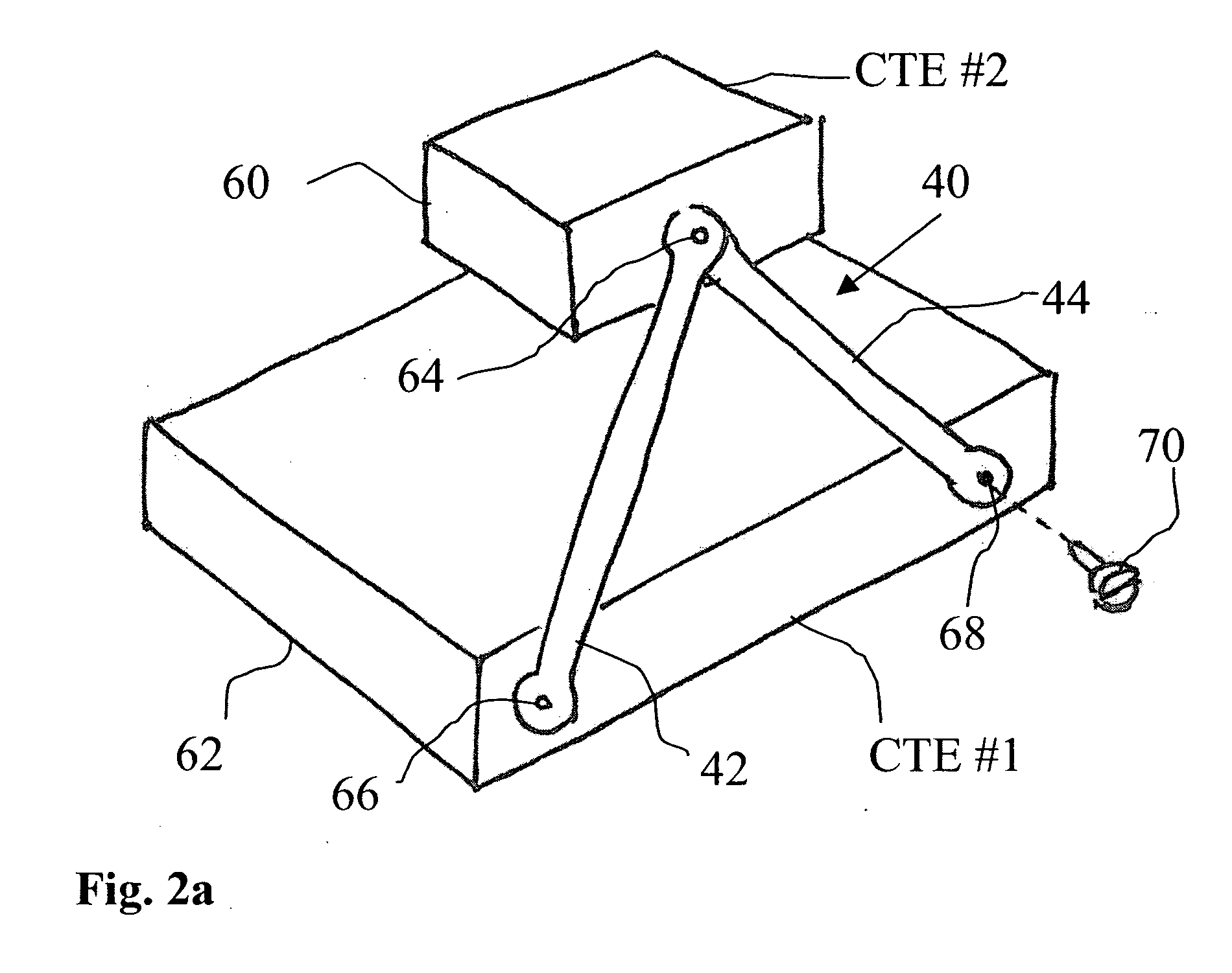
While flexure mounts have proven utility for maintaining positional accuracy to prevent unwanted shifting of components in many types of applications,
adaptation of this type of mounting to thermal excursion applications introduces additional requirements.
Among the challenges that complicate such a solution is the likelihood that color separator prism 20 and its associated mounting hardware exhibit a coefficient of
thermal expansion (CTE) that is different from the CTE of supporting
chassis components.

