Drive belt pulley and belt drive system

a belt drive and belt pulley technology, which is applied in the direction of gearing, couplings, hoisting equipment, etc., can solve the problems of fuzzing, flat belt side face, wobbling and sidetracking, etc., and achieve the effect of reliable prevention of wobbling and sidetracking and effective utilization of belt drive systems

Inactive Publication Date: 2005-03-31
BANDO CHEM IND LTD
View PDF13 Cites 5 Cited by
  • Summary
  • Abstract
  • Description
  • Claims
  • Application Information

AI Technical Summary

Benefits of technology

[0014] With the foregoing in mind, the present invention aims at enabling reliable prevention of wobbling and sidetracking of flat belts or other drive belts and in turn at effective utilization of belt drive systems for various kinds of industrial machines and other equipment.
[0015] To achieve the above aim, the present invention prevents sidetracking and wobbling of a drive belt by changing the attitude of a pulley appropriately using the phenomenon that the center of radial load on a pulley shaft changes by tension of the drive belt when the drive belt deviates to one side of the pulley.

Problems solved by technology

In drive systems using a flat belt, the flat belt when running often causes wobbling and sidetracking towards one side of the pulley.
This is because a flat belt is susceptible, as compared with the other kinds of drive belts, to position changes of drive system components, such as deviation of a pulley shaft from its normal position, deflection thereof due to change in radial load thereon, and pulley wobbling.
If such a belt wobbling or sidetracking occurs, then the flat belt may come into contact with a flange of the flat pulley, resulting in a fuzzed flat belt side face or a frayed cord.
This prevents effective utilization of the entire belt width for power transmission and leads to early cord fatigue and degraded power transmission performance.
The above-mentioned technique of forming the pulley crown into a sphere around the rotation center of the pulley, even if it enhances the effect of preventing sidetracking of a drive belt, still has the above problem that stress is focused on the middle of the belt width by the pulley crown.
The above-described grooving of the flat pulley surface raises the production cost of the flat pulley.
In addition, it is difficult to certainly prevent wobbling and sidetracking of the flat belt simply by the grooving.
As a result, the belt side face is likely to fuzz and the cord is likely to fray.
This creates the need for applying to the flat belt a special process for preventing such adverse effects, which is a disadvantage to reduction of production cost of the flat belt.
For the above-described reasons, the fact is that though flat belt drive systems have lower loss due to belt flexing and very higher power transmission efficiency as compared with systems using other types of belts, such as V-belts, they are not exploited enough.

Method used


Image

  • Drive belt pulley and belt drive system
  • Drive belt pulley and belt drive system
  • Drive belt pulley and belt drive system

Examples


Embodiment Construction

[0074] Hereinafter, embodiments of the present invention will be described in detail with reference to the drawings.

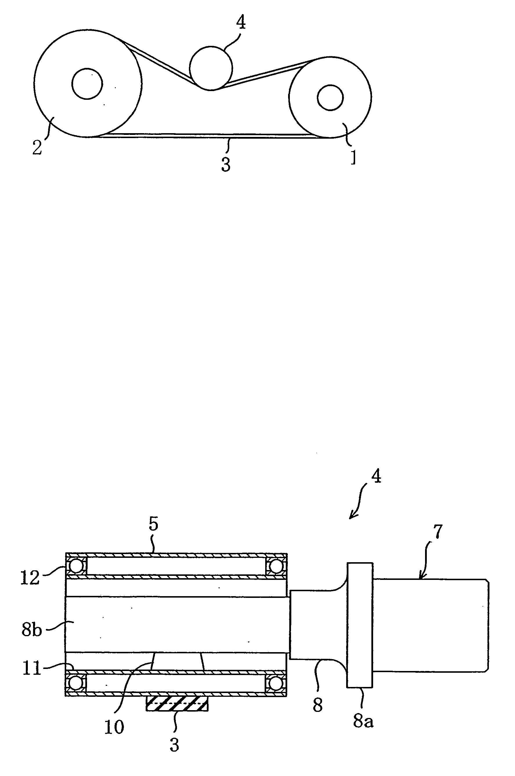
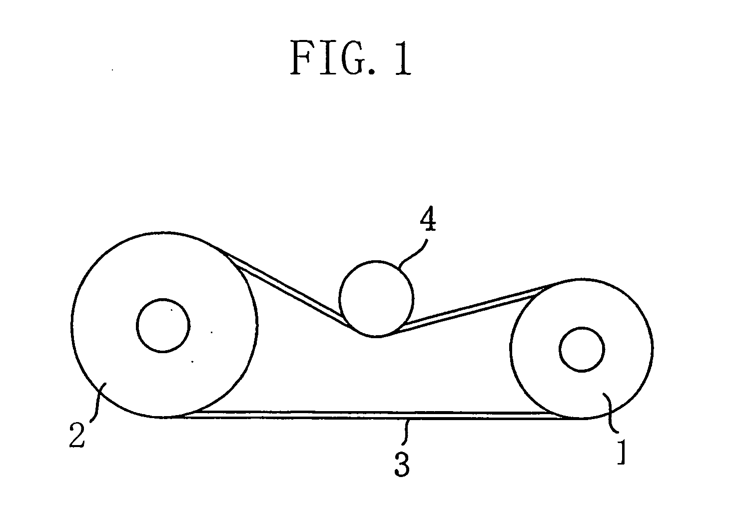
[0075] In a belt drive system of a first embodiment of the invention shown in FIG. 1, reference numeral 1 denotes a drive pulley (flat pulley), and reference numeral 2 denotes a driven pulley (flat pulley). A drive belt (flat belt) 3 is wrapped around both the pulleys 1 and 2. A drive belt pulley 4 is pushed against the back face of the drive belt 3 in order to apply tension to the drive belt 3.

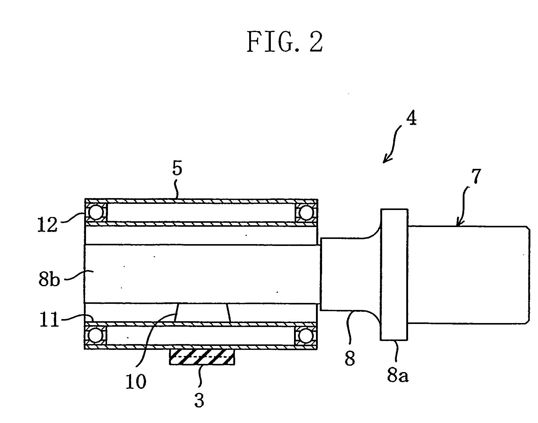
[0076] As shown in FIG. 2, the pulley 4 has a hollow cylindrical pulley body 5 around which the drive belt 3 is to be wrapped, a hollow cylindrical shaft member 11 that rotatably carries the pulley body 5 via bearings 12, and a support member 7 that supports the shaft member 11. The support member 7 is provided with a support rod 8 and a rubber elastic body 10.

[0077] The support rod 8 consists of an attachment part 8a and a supporting part 8b continued from one end of the att...


PUM


Abstract

A hollow cylindrical pulley body 5 is carried rotatably by a hollow cylindrical shaft member 11. A support rod 8 is inserted in the shaft member 11, and the shaft member 11 is elastically supported to the support rod 8 through an elastic body 10. The elastic body 10 is provided within a quarter of the periphery of the support rod 8 that is located, when viewed along the axis of the shaft member 11, forward of the line of action of a radial shaft load on the shaft member 11 with respect to the direction of rotation of the pulley body 5. With this configuration, when the drive belt 3 deviates to one side, the pulley body 5 is immediately angularly moved so that it is inclined with a level difference with respect to the direction of the radial shaft load and is positioned obliquely relative to the drive belt 3. In this manner, a force of compensating for the deviation of the drive belt 3 is produced to avoid its wobbling.

Description

CROSS-REFERENCES TO RELATED APPLICATIONS [0001] This application claims priority under 35 USC 119 to Japanese Patent Applications No. 2003-335716 filed on Sep. 26, 2003 and No. 2004-60354 filed on Mar. 4, 2004, the entire disclosure of each of which, including specification, drawings and claims, is incorporated herein by reference in its entirety. BACKGROUND OF THE INVENTION [0002] (a) Field of the Invention [0003] This invention relates to drive belt pulleys and belt drive systems. [0004] (b) Description of the Related Art [0005] In drive systems using a flat belt, the flat belt when running often causes wobbling and sidetracking towards one side of the pulley. This is because a flat belt is susceptible, as compared with the other kinds of drive belts, to position changes of drive system components, such as deviation of a pulley shaft from its normal position, deflection thereof due to change in radial load thereon, and pulley wobbling. If such a belt wobbling or sidetracking occur...

Claims


Application Information

Patent Timeline
Patent Type & Authority Applications(United States)
IPC IPC(8): F16H7/08F16H7/12F16H7/18F16H55/54F16H55/36
CPCF16H7/12F16H2007/0865F16H55/36F16H7/18Y10S474/902
Inventor MIYATA, HIROFUMINISHIKAWA, SHINICHIROYOSHIMURA, MASASHI
Owner BANDO CHEM IND LTD
Why Eureka
Try Eureka