Disk device having clamp mechanism

a technology of clamping mechanism and disk, which is applied in the field of disk devices, can solve the problems of conventional clamping devices, and achieve the effects of enhancing the magnetic force of the magnet housed, enhancing the magnetic force of the magnet, and improving the attractive for

Inactive Publication Date: 2005-03-31
ORION ELECTRIC CO LTD
View PDF4 Cites 9 Cited by
  • Summary
  • Abstract
  • Description
  • Claims
  • Application Information

AI Technical Summary

Benefits of technology

[0016] Thus, the conventional clamp device has the problems described above. The invention contemplates to solve those problems and has an object to provide a disk device having a clamp mechanism, which can correctly clamp a disk mounted on a turntable, which can regulate eccentricity at the turning time and can prevent slips and facial vibrations, and which can prevent a clamper from becoming loose during the turning motions.
[0018] The distance between the lower face of the retention member and the upper edge of the cylindrical rib may be made equal to or slightly smaller than the thickness of the cover. As a result, the fitting relation between the bulge of the lower face of the retention member and the engagement portion of the cover can be made reliable so that the relation is neither broken nor loosened during the rotation of the clamper.
[0019] A magnetic member may be mounted on the turntable and can attract the magnet disposed in the clamper to each other. The cover may be manufactured by punching out an iron sheet so that it prevents the magnet mounted in the clamper from being demounted and exhibits not only the clamper-supporting role but also a function to enhance the magnetic force of the magnet. In other words, a back yoke is established to improve the attractive force to attract the magnetic member on the turntable side.
[0020] According to the disk device having the clamp mechanism of the invention, the bulges formed on the lower faces of the retention members of the hook portions disposed at the clamper engage with the engagement portions of the cover so that the cover neither comes out of the clamper nor releases the housed magnet. Moreover, the cover neither becomes loose nor rotates eccentrically so that it can prevent the slip of the rotating disk, the vibrations and the facial vibrations.
[0021] The cover is made of a magnetic material such as iron so that it can enhance the magnetic force of the magnet housed in the clamper thereby attracting the magnetic member of the turntable more forcibly. Moreover, the works to mount the cover can be simply performed merely by inserting the hook portions of the clamper into the insertion portions and turning them to the engagement portions, and the demounting works are also facilitated. At this time, the burrs, which are left after punched by a press in the engagement portions, the communication portions and the insertion portions of the cover do not fall as chips.

Problems solved by technology

Thus, the conventional clamp device has the problems described above.

Method used


Image

  • Disk device having clamp mechanism
  • Disk device having clamp mechanism
  • Disk device having clamp mechanism

Examples


Embodiment Construction

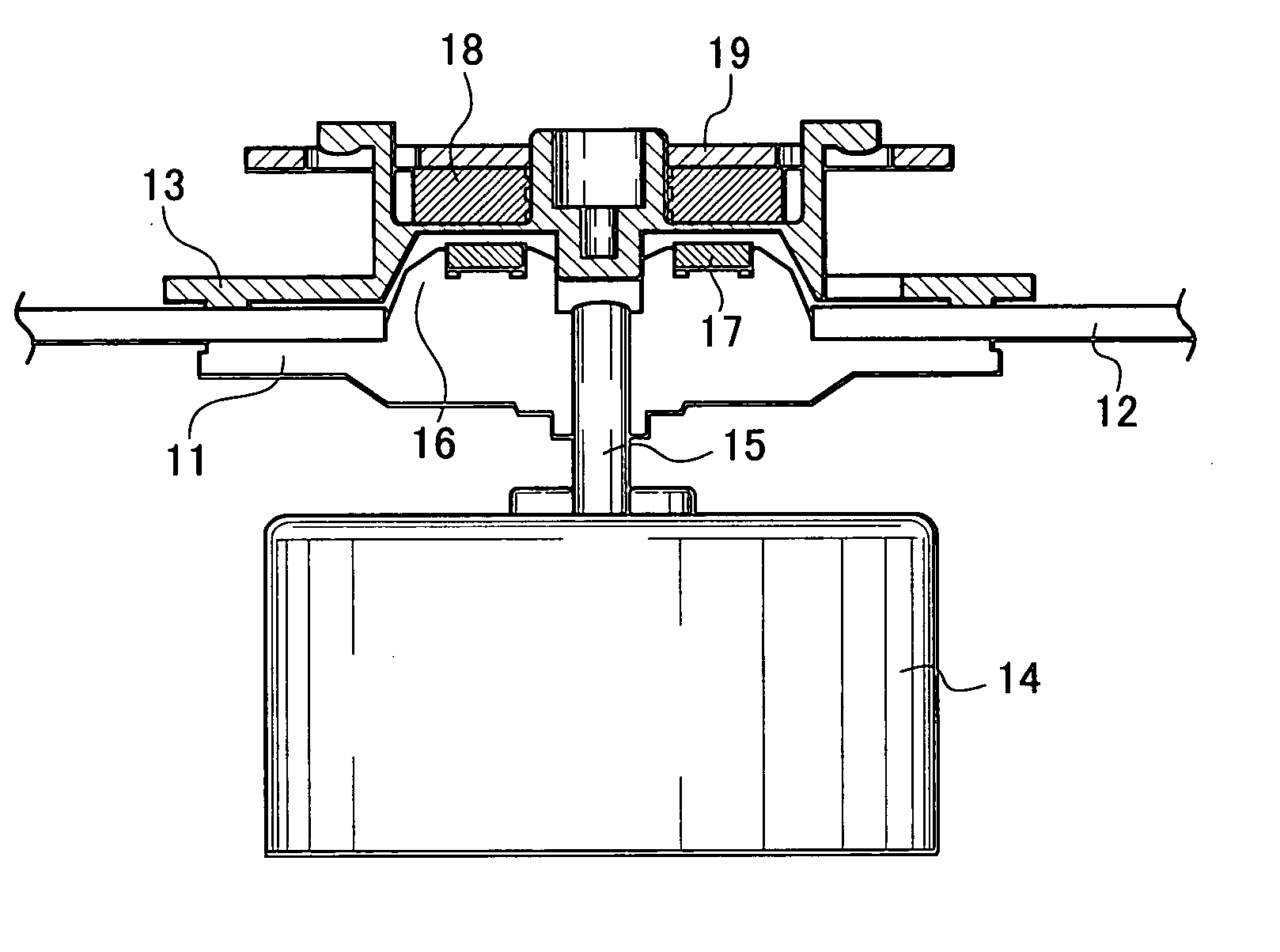
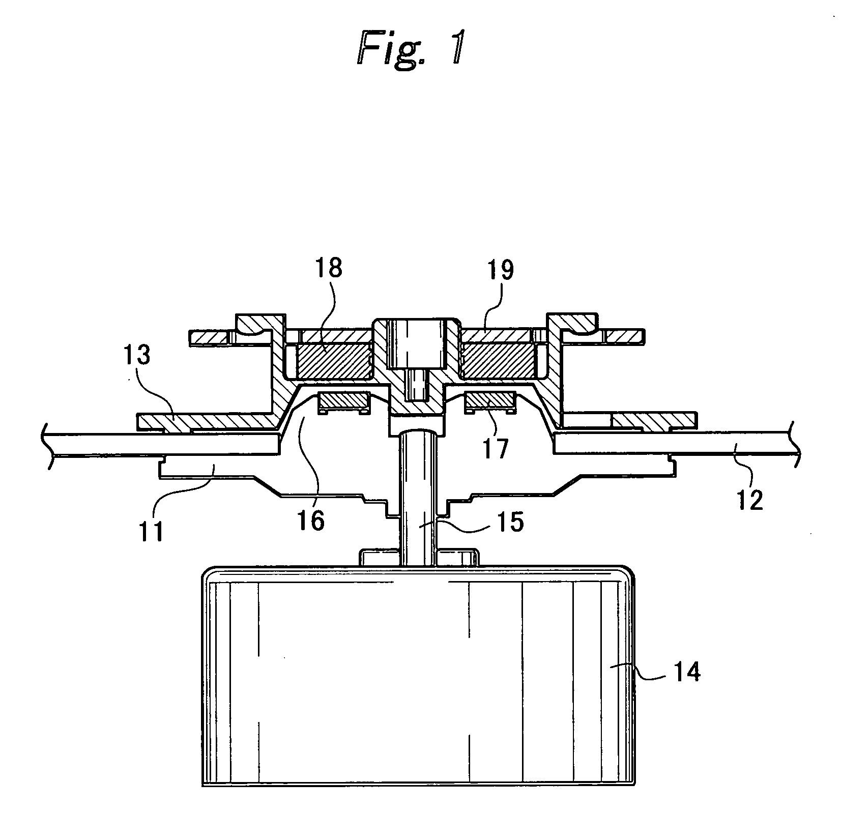
[0029]FIG. 1 shows the state, in which a disk 12 is mounted on a turntable 11 of a disk device and clamped by a clamper 13. The turntable 11 is mounted on a spindle 15 of a motor 14. The central portion of the disk-shaped turntable 11 is formed an upward bulge 16, and a magnetic member 17 is mounted on the upper face of the bulge 16. The disk 12 is provided at its center with a hole, in which the center bulge 16 of the turntable 11 is fitted so that the disk 12 is correctly mounted in position on the turntable 11.

[0030] Moreover, the disk 12 is pushed downward by the clamper 13 so that it may not be demounted from the turntable 11. This pushing force is exemplified by the magnetic force of a magnet 18 housed in the clamper 13. Specifically, the magnet 18 and the magnetic member 17 mounted on the turntable 11 attract each other so that the clamper 13 exerts the pushing force on the face of the disk 12. The ring-shaped magnet 18 is housed in a cylindrical rib formed in the central po...


PUM

PropertyMeasurementUnit
circumferenceaaaaaaaaaa
thicknessaaaaaaaaaa
speedaaaaaaaaaa

Abstract

To provide a disk device having a clamp mechanism, which can correctly clamp a disk mounted on a turntable, which can regulate eccentricity at the turning time and can prevent slips and facial vibrations, and which can prevent a clamper from becoming loose during the turning motions, the clamp mechanism comprises a clamper integrally formed of a resin material, a magnet and a cover. The clamper includes a disk-shaped clamp unit, a cylindrical rib formed at the central portion of the clamp unit, a bottom plate formed a housing space to house the magnet in the rib and to be covered by the cover, a boss projected from the lower face side of the center of the bottom plate and adapted to be fitted and positioned in a recess of the upper face of a turntable. The cylindrical rib is provided on its upper edge with at least two such L-shaped hook portions at equal intervals as each includes a connection member extended vertically and having a bulge on its lower face, and a retention member extended horizontally outward from the leading end of the connection member. The cover is provided in its outer circumference with engagement holes at positions individually corresponding to the hook portions. Each of the engagement holes includes a communication portion for allowing the connection member of the corresponding hook portion to pass therethrough, an insertion portion formed to communicate with one end side of the communication portion for inserting the corresponding hook portion, and an engagement portion formed to communicate with the other end side of the communication portion and made smaller than the retention member of the corresponding hook portion, for fitting the bulge on the lower face of the retention member of the corresponding hook portion.

Description

BACKGROUND OF THE INVENTION [0001] 1. Field of the Invention [0002] The present invention relates to a disk device, which is characterized in a clamp mechanism for clamping a disk on a turntable. [0003] 2. Related Art [0004] The disk device is enabled to read signals recorded in a disk by using an optical pickup. In this case, the disk device is constructed such that the disk is mounted on the turntable and is turned after clamped, and such that the optical pickup is moved at a predetermined speed in the radial direction of the disk. The turntable is directly connected to the spindle of a drive motor so that it is turned at a high speed. If the disk is merely mounted on the turntable, it may go out of position during the turns, or a slip may occur between the disk and the turntable thereby causing a phase difference in the angular velocity. Thus, the disk device is made to clamp the disk. [0005] A clamper of the clamp mechanism is rotatably born to rotate together with the turntable...

Claims


Application Information

Patent Timeline
Patent Type & Authority Applications(United States)
IPC IPC(8): G11B17/028
CPCG11B17/0284
Inventor ASABATA, TATSUHIRO
Owner ORION ELECTRIC CO LTD
Why Eureka
Try Eureka